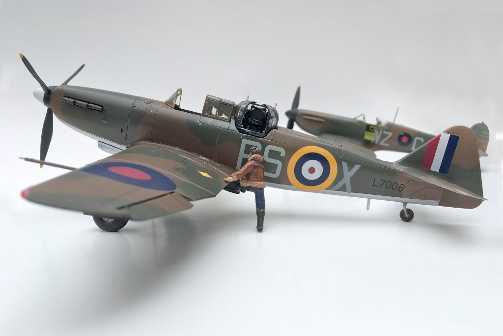
The Hawker Sea Harrier became a well deserved legend during the Falklands War. With a little extra work the 1/48 scale Airfix kit deserves a place in your collection.
In the late afternoon of May 1, 1982 Royal Naval Air Service Hawker FRS-1 Sea Harriers went up against enemy fighters for the first time during “Operation Corporate” the war to take back the Falkland Islands. The revolutionary fighter had never seen combat before. It was a unique aircraft, able to take off vertically and transition to level flight. It would prove more than a match for Argentine Mirage, Dagger and A-4 Skyhawks in the freezing skies of the South Atlantic. By the end of May, the Sea Harriers had dispatched 20 Argentine aircraft for no loss, in air-to-air combat.
The Kit
The 1/48th-scale Airfix Sea Harrier FRS.1 has been around for quite a while. Although there have been some stellar new releases—I would love to see an retooled Airfix kit! —for now I’ve concentrated on adding a little after-market detail to improve this build. Some scratch-building skills will come in handy for this project.
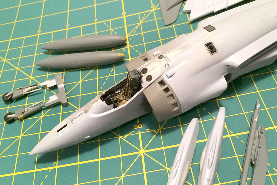
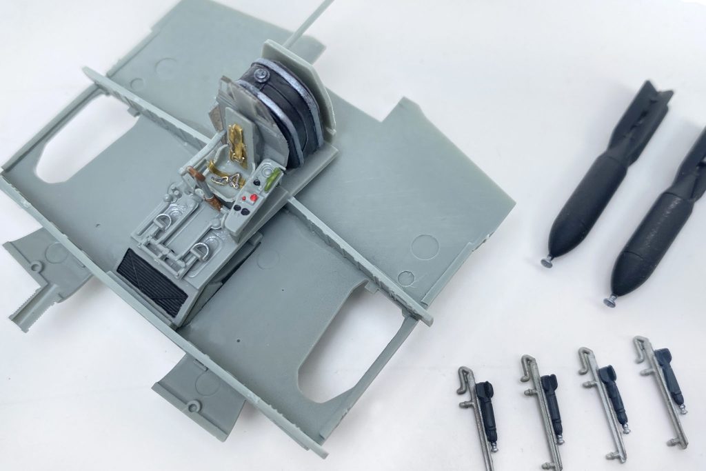
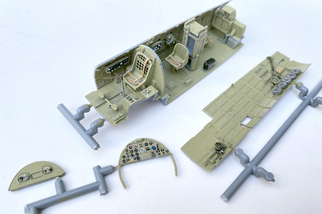
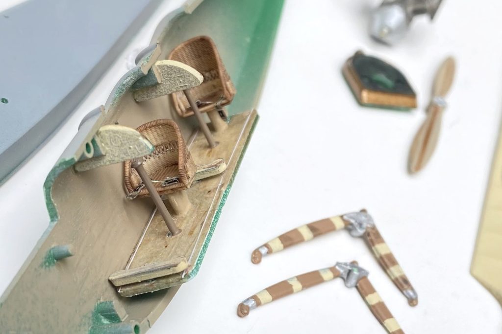
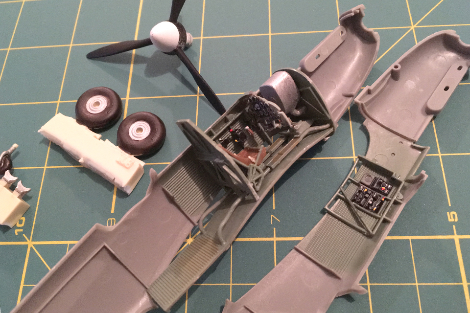
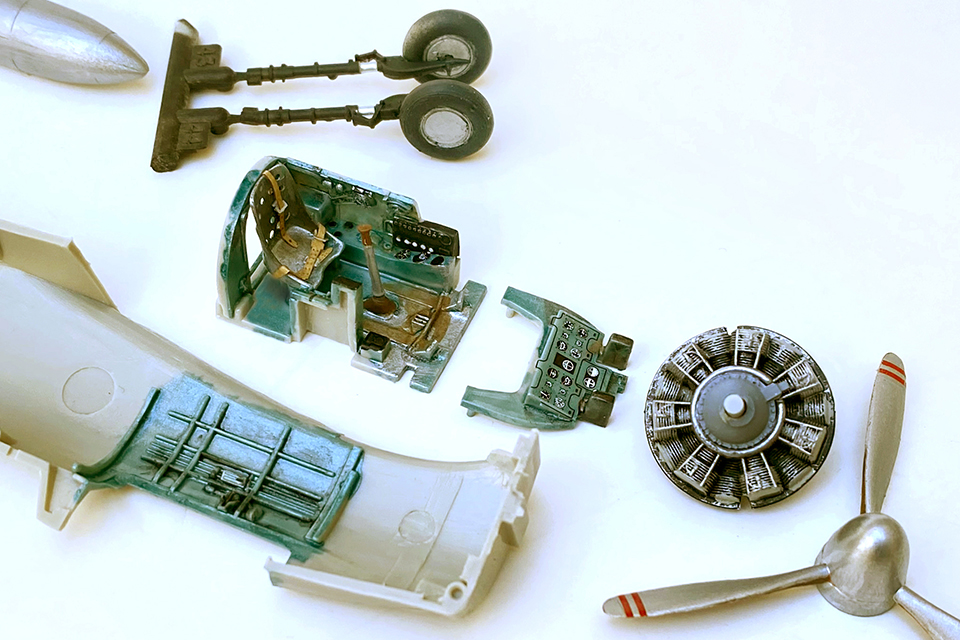
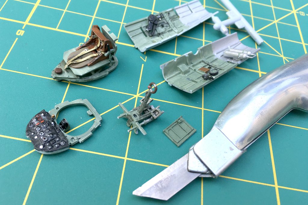
I replaced the stock seat with a resin version, and the rest of the cockpit was enhanced with an etched-metal detail set. The other bumps, tubing, wiring, etc. came from my parts box. Note that the gun pods need some additional detail: I added a new gun muzzle and drilled out the four vents just aft of the muzzle. I also opened up the auxiliary power unit exhaust vent, on top of the fuselage, and added a set of aftermarket intakes to accurately depict what a powered-down engine would look like. An AIM-9L Sidewinder came from the parts box.
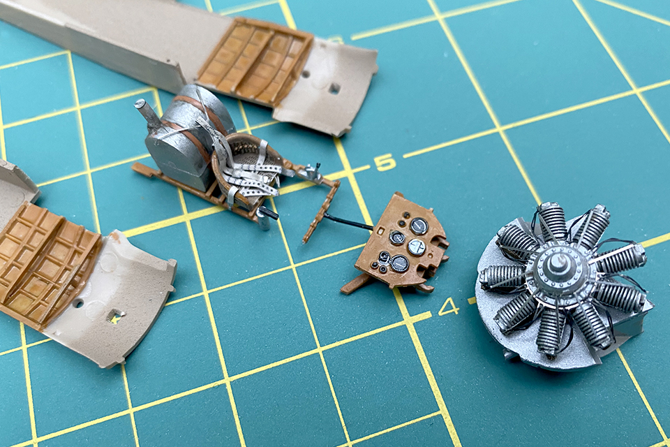
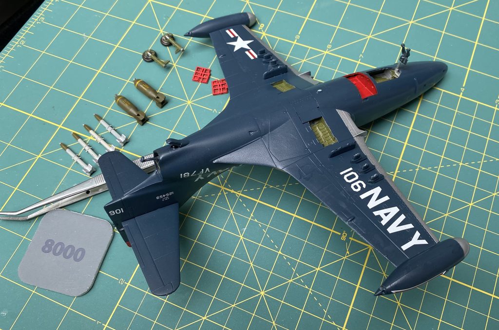
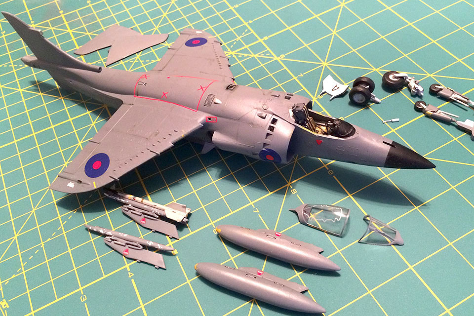
Taking a break from all that fine detail work in the cockpit, I spent some time finishing off some of the smaller bits, so they would ready for final assembly. These included the landing gear, the extra fuel tanks, the pylons and the AIM-9 missiles.
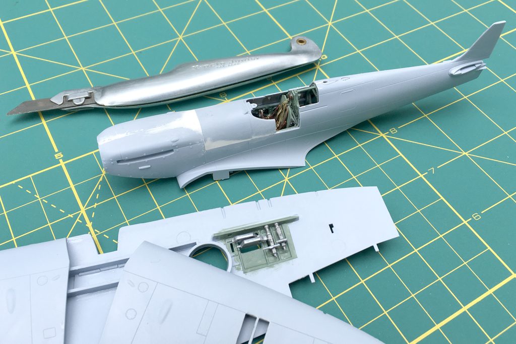
Once the cockpit is complete, the wings and fuselage come together. Then it’s time for filling and sanding—plenty of it. But that’s what you expect with a kit that’s some 30 years old.
Air War South Atlantic
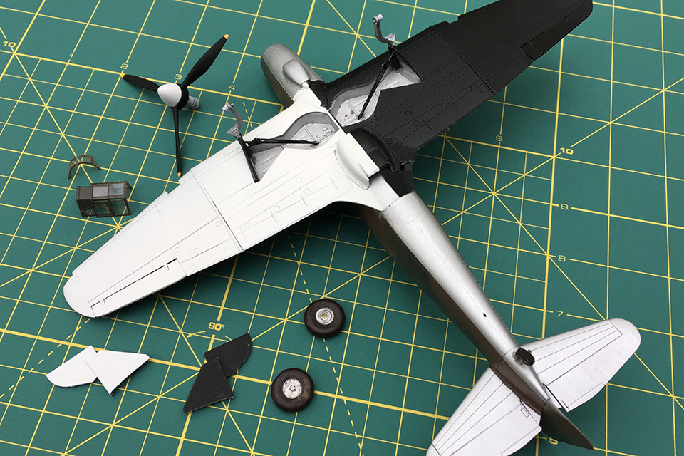
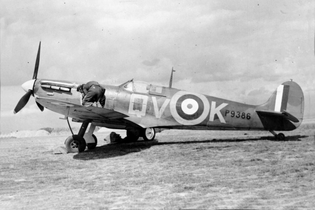
The Hawker Harrier’s introduction was an aviation milestone, combat during the Falklands War in May 1982 that gave the fighter its “street cred.” At the heart of the Harrier’s unique capabilities is its Pegasus engine. Four nozzles rotate to direct the exhaust, putting the “vertical” in VTOL. Cooler air leaves the forward two nozzles, while hotter exhaust comes from the rear two. The rear pair should be painted a smoked metallic color, and the forward nozzles should be a color similar to the jet’s camouflage tone. During the Falklands War, the first group of Sea Harriers to head from Britain to the South Atlantic lost their more visible dark sea gray and white along with their colorful squadron markings in favor of overall dark gray. The new paint scheme was applied during their voyage south.
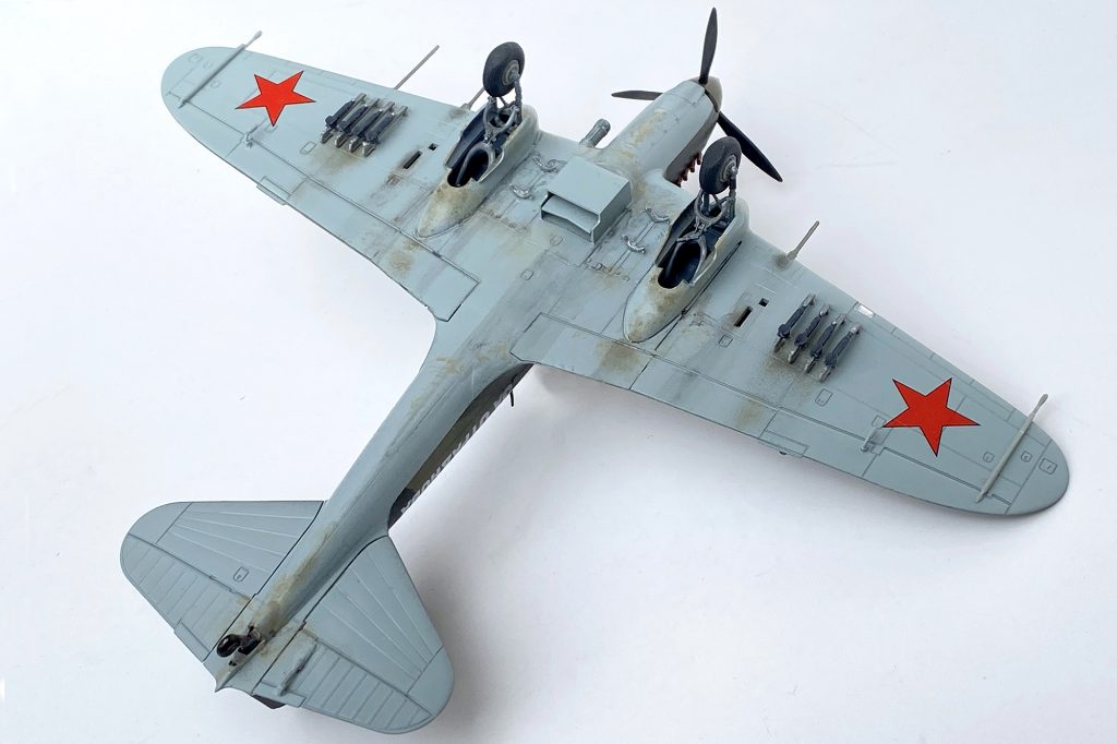
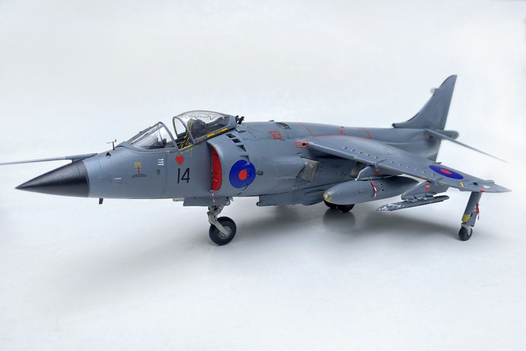
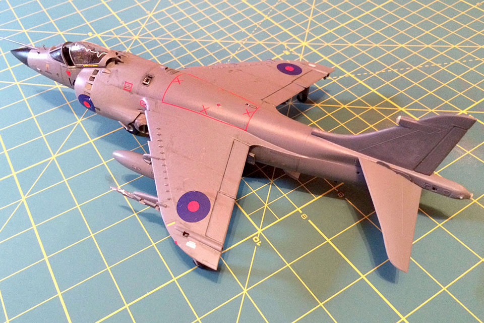
With wings attached to the model, the cockpit masked off and filling and sanding complete, it’s time for paint. I chose an overall dark gray that fits my reference material. Once I applied a coat of a gloss varnish, it was time to start on the kit’s excellent decals. Though they’re thin, they respond well to a little decal softener, snuggling into all those nooks and crannies.
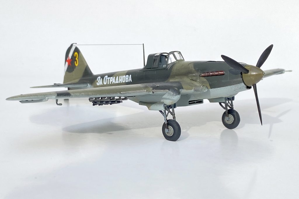
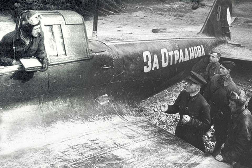
Markings for a Combat Vet
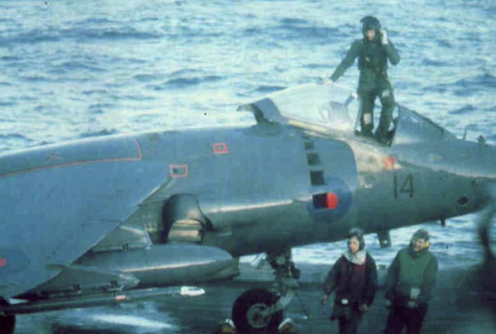
The kit comes with a choice of markings: an aircraft from the Indian Naval Air Force or XZ457 (“Black 14”), a Royal Naval Air Service Sea Harrier that flew from the carrier HMS Hermes during the Falklands conflict and was credited with two Argentine IAI Daggers and an A-4 Skyhawk. Interestingly, both Black 14 and the Indian jet spent time aboard Hermes, as the carrier was sold to India in 1987.
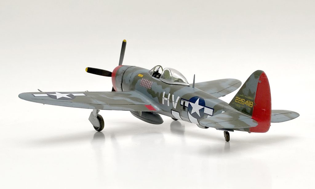
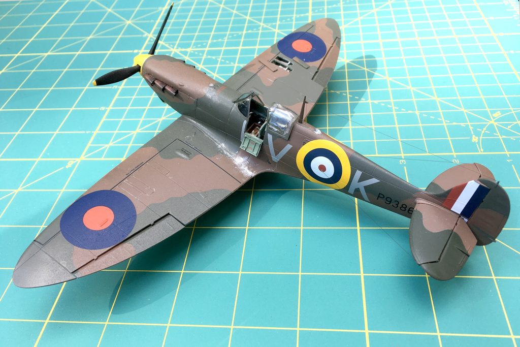
I took care of the trickier decals under the wings and some other hard-to-reach places before adding underwing stores and the landing gear. Much of the stenciling on this jet was painted over as Hermes headed into combat. Note that special care is required when positioning the landing gear to get the jet to stand evenly on all four points. Take your time with this process.
Finally, superglue the remaining antennas in place, then add a little weathering, and your Harrier is complete. With patience and a little finesse, this classic Airfix kit will make a nice addition to your collection.