Designed to support Soviet ground forces, the Ilyushin Il-2 was produced in greater numbers than any other airplane in history, bad news for German armor rumbling across the battlefield.
The Flying Tank
Designed by the legendary Sergey Ilyushin, the Il-2 was designed to support Soviet ground forces and was nicknamed Shturmovik (штурмовик), a generic term for a ground-attack aircraft that became synonymous with the airplane. Referred to as “Stalin’s Tank” and “Hunchback” because of the shape of the cockpit, the heavily armored airplane packed a solid punch. A big, broad wing gave the airplane the lift it needed to carry enough rockets and bombs to hunt German panzers across the broad plains around Kursk in July and August 1943. Solid construction helped it survive both flak and encounters with the Luftwaffe’s best.
The airplane was introduced to frontline service in May 1941 just weeks before the Operation Barbarossa, the invasion of the Soviet Union by Nazi Germany on June 22, 1941. While only 249 aircraft were available at the time, by the end of the war over 43,000 had been built, one of the most produced aircraft in aviation history. The “Flying Tank” was built in a number of types including a two seat version with the addition of a rear gunner.
The Kit
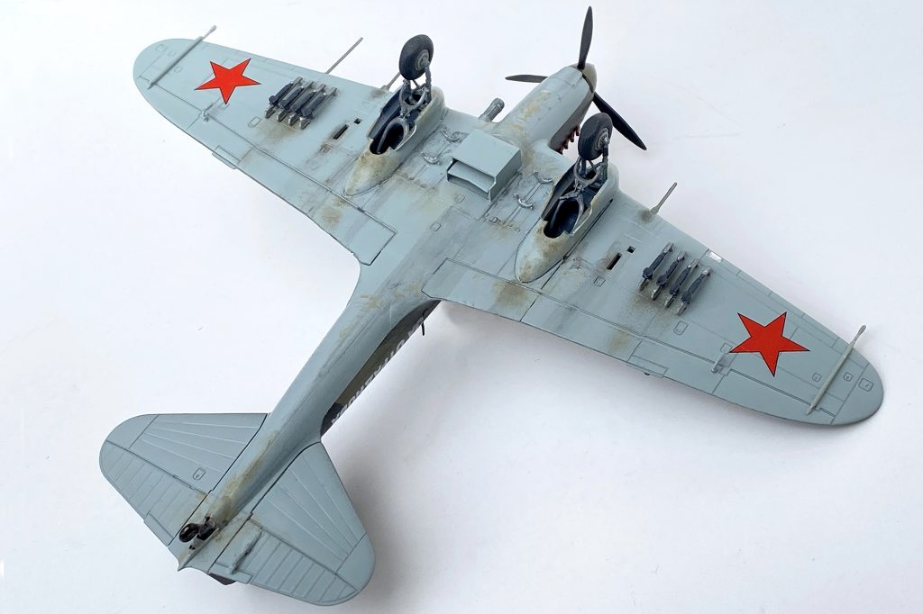
The Academy 1/72nd-scale Sturmovik was released as both a single-seat Il-2 and as a two-seat Il-2M. it includes a variety of armament including air-to-ground rockets, a pair of 220 lb bombs, and small bomb bays that would contain over 100 anti-armor bombs. The kit has very nice detail and good fit, needing a minimal amount of filling and sanding.
First Things First
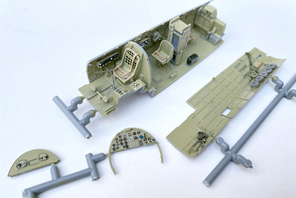
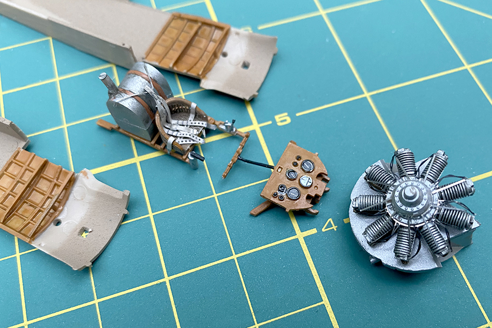
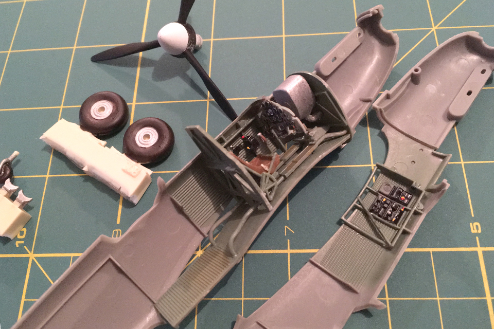
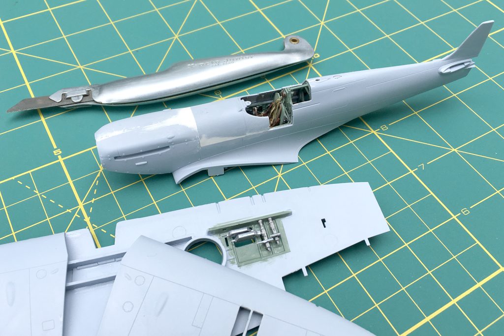
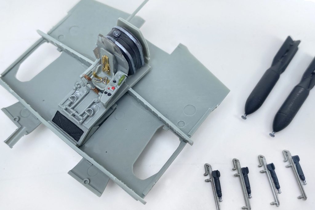
This kit is the single seat Il-2 but the start of the build is the same, the cockpit. Fit the seat, rudder pedals and the large gas tank situated behind the pilot’s seat to the cockpit floor. A couple of strips of painted masking tape can work as a set of seat belts and a shoulder harness. The cockpit assembly sits on the center section of the lower wing. The wing/cockpit assembly fits into the two fuselage halves when they’re glued together. Don’t forget to install the control panel before cementing the cockpit and lower wing into place.
At this point the instructions call for the engine exhaust (parts F9) to be glued from the inside of the fuselage halves. A better choice is to wait until the fuselage is painted, trim the parts and install them after painting. The direction sheet also shows where wing-mounted machine guns (parts F96) fit into the wing. Again, wait until later to add these tiny parts.
Make Sure Things Fit
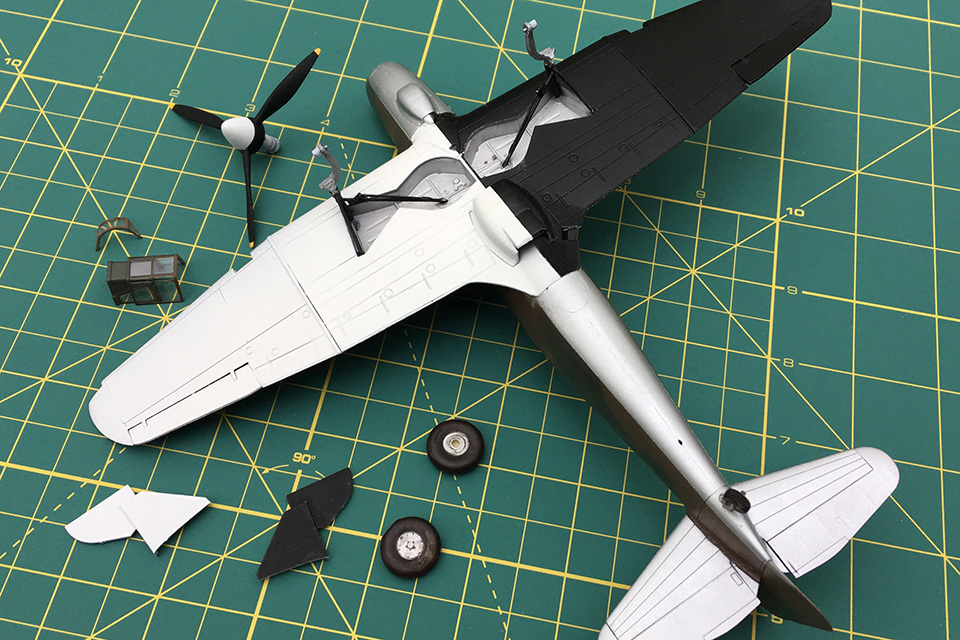
Take some time to dry-fit the rest of the wing. Keep an eye on the fit at the wing root. With the wing attached to the fuselage, add the landing gear bays to their positions on the underside of the wing. Fill and sand the fuselage and wings; smooth out the seams around the landing gear, wing root and fuselage; and then set the assembly aside.
Put together the tires, painting them flat black with aluminum-colored hubs. Assemble the two 500-pound bombs, painting them black as well. This Il-2 is also armed with eight unguided rockets on launch rails beneath the wing. Paint the rockets dark gray with silver tips and the individual rails steel. After assembling the propeller, paint the blades black and the spinner dark green.
Painting
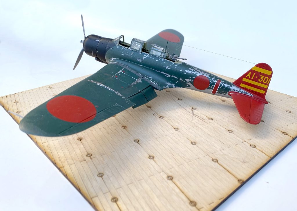
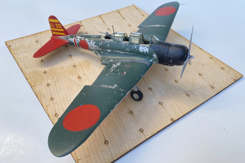
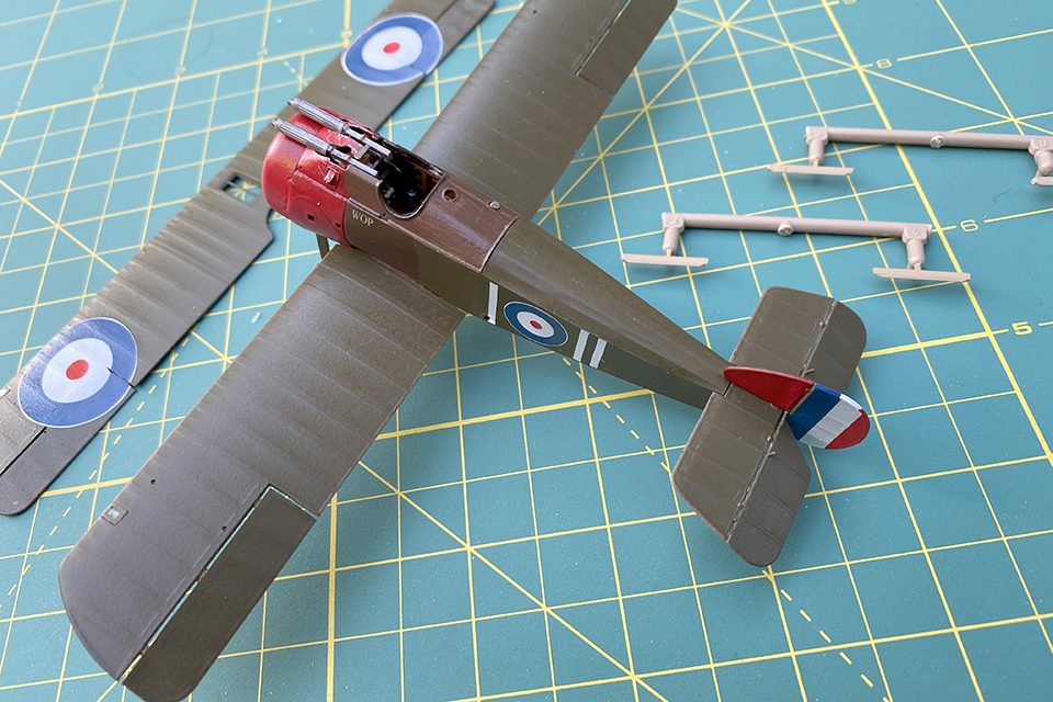
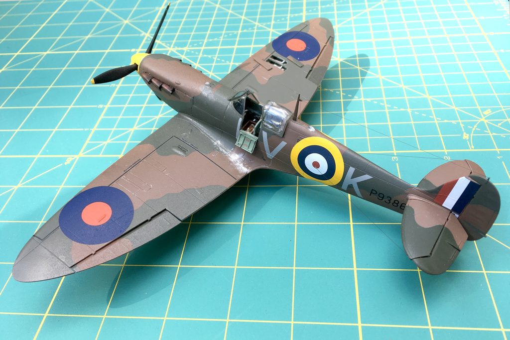
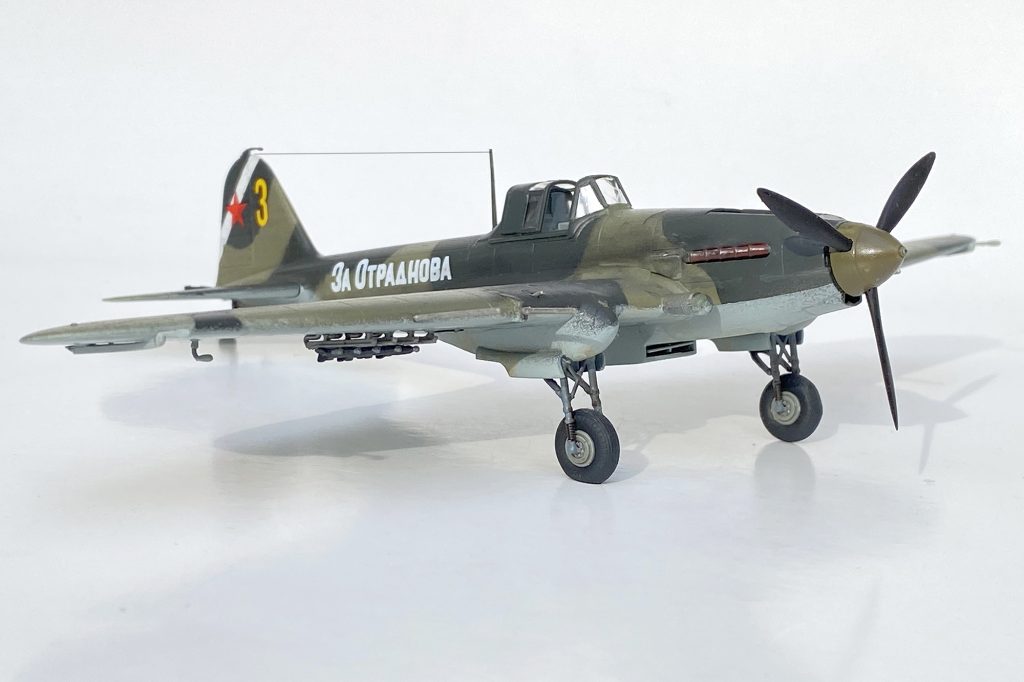
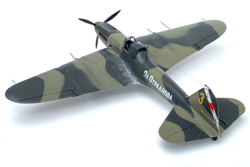
Now it’s time to mask off the cockpit and paint. The Academy kit has a choice of 11 different aircraft markings in a variety of camouflage schemes. This one will be painted with a medium olive drab and a very dark, greyish-green pattern on the upper surfaces with light blue on the undersides.
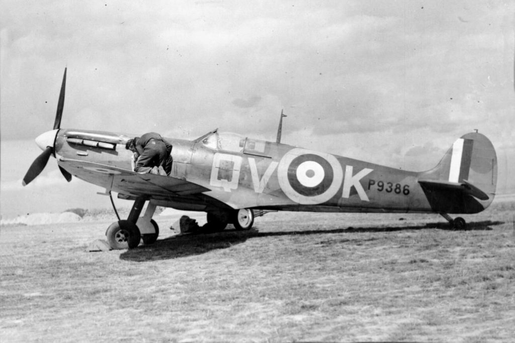
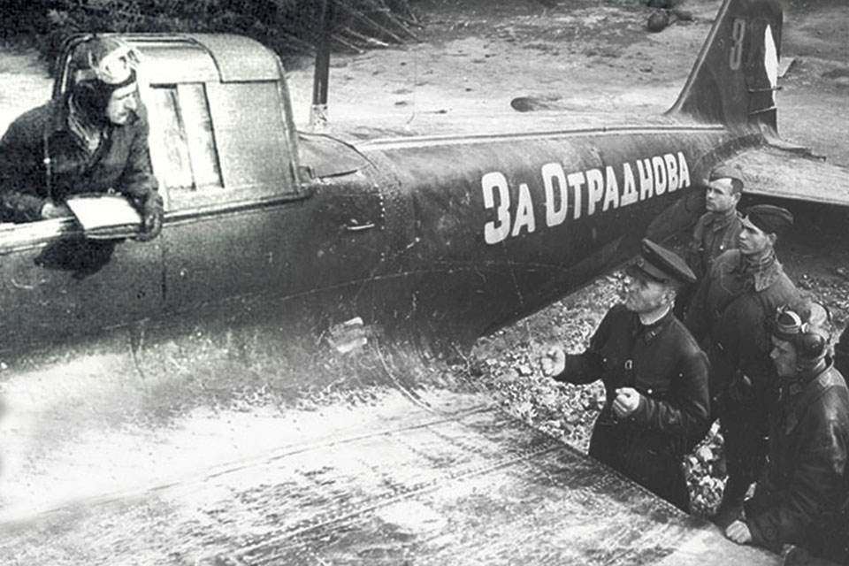
Once all the masking has been peeled away to show the completed camouflage, a number of “tiny bits” need to be added. The trim tab actuators are separate pieces that require special care when gluing each (very tiny) piece onto the wings and tail surfaces. Touch up the camouflage and spray the model with a coat of clear gloss to prepare it for the decals. This Sturmovik had the words “За Отраднова” (For Otrandova) painted down the side of the fuselage in honor of a fellow pilot named Otrandov, probably killed in battle. Note that the iconic red star insignia does not appear on the top of the wing, only on the undersurfaces and tail.
A modest amount of weathering lends some authenticity to this Il-2. These aircraft spent a lot of time in the field and would have seen plenty of use. Chipped paint along the left wing root shows where crew and maintainers spent time getting in and out of the airplane. Exhaust stains and soot under the wing mark where rockets had been launched at previous targets. All these things will give the model plenty of interest.
It’s time to install the landing gear. Be careful clipping these pieces from the “parts tree,” as they are delicate and can easily break. Carefully cement the two braces that make up the landing gear struts into the “pods” underneath the wing. The fit is tight—dry-fit a couple of times before final assembly. Once they set thoroughly, add the tires, which fit neatly on the forward struts. The tires come slightly flattened to show the weight of the aircraft once it’s completed. Make sure the airplane sits correctly before adding a small bit of cement to the tires, completing the landing gear.
At this stage you can insert the two exhaust stacks into place. Carefully slip those tiny machine gun barrels and longer cannon barrels onto their positions at the wing’s leading edge. Paint them a light gunmetal color. Add the propeller and set the nearly completed model aside.
With a very sharp knife mask the three-part clear canopy. Modeler’s masking tape is a good choice for those with a steady hand. Pre-cut masks are another option and can be obtained from a number of retailers. With the clear parts painted, use white glue, or a cement formulated for clear parts, and add the canopy.
Time to load this tank killer up. Attach the eight unguided rockets and launch rails to their positions under the wings. Bomb braces have positions between the landing gear and fuselage. Add the braces and then attach the bombs.
Finally, mount the radio antenna just behind the cockpit and this Il-2 is ready to hunt for German panzers across the Russian steppes.