A Ground-to-Air Pilotless Aircraft? Building Boeing’s BOMARC

Atlantis Hobbies brings back a classic Cold War kit and it’s great nostalgia.

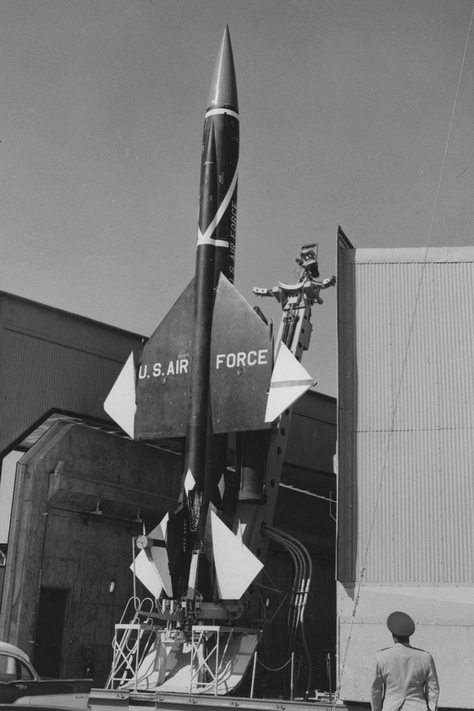
The Bomarc surface-to-air missile was a Cold War response to the apocalyptic vision of squadrons of Soviet bombers headed toward targets in North America. A nuclear-tipped interceptor streaking toward the enemy seems the stuff of science fiction today, but in the 1950s it was an all too real strategy. 

During the post World War II boom, things seemed to get … bigger. Cars got bigger, houses got bigger, even the portions at the local diner got bigger, and so did surface-to-air missiles. By the end of the war experiments with anti-aircraft missiles led to a number of concepts, technology being what it was (before the microchip) many proposals were as large as the early jet fighters of the day. Boeing’s ramjet powered MX 1599 was just one of those designs. The Air Force thought the idea was promising and, emphasizing that it was essentially a pilotless aircraft, gave it the designation F-99. 

Testing lasted through 1955 and the early versions of what was now designated the IM-99A, got the nickname BOMARC (Boeing Michigan Aeronautical Research Center). The project mirrored some US Army projects, and created more than a little inter-service rivalry, but this was clearly the air force’s baby. 

BOMARC was declared operational in 1959, and while the Air Force wanted to create as many as 52 sites around the country defending major US cities, only 14 were built in the US and two in Canada, our North American Air Defense Command (NORAD) partner. As defense budgets decreased cuts followed some of the maintenance issues (and an accident or two). Missile sites began to be deactivated and the last operational site at McGuire AFB, New Jersey was closed down in 1972.

BOMARC remains a fascinating story of weapons development during the height of the Cold War. This faithful replica will make a great source of conversation on a modeler’s display shelf.

The Kit

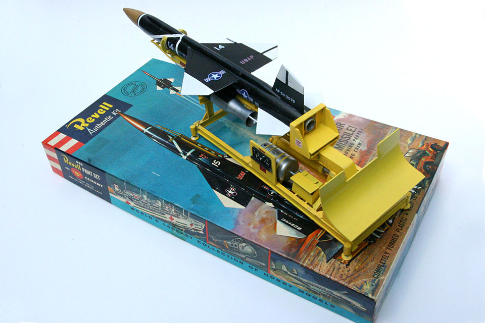
Revell released their IM-99 Bomarc kit in 1958. Fortunately for us, the classic Cold War missile is back on hobby shop shelves thanks to the Long Island company, Atlantis Hobbies. The kit comes complete with the original box art by the legendary artist Jack Leynnwood. The parts are exactly the same as they were when the kit first hit the shelves. Ah, nostalgia.

The artwork by Jack Leynnwood, used in the original Revell release was rescued by Atlantis Hobbies and adorns their re-release.

Gather up four or five grades of sandpaper and get to work. Assembly of the missile is relatively simple, since only a dozen pieces make up the actual weapon. There is some minor flash and a few ejector pin marks, typical of older kits. Rather heavy rivets and deep panel lines will need to be sanded down. The fit is ok but seams will still need some putty, more sanding and then…some more sanding. After the fuselage, wings and tail come together, it’s time for…a little more sanding. A coat of primer or a product like Mr. Surfacer will help reveal spots that need additional filling and sanding. The two ramjet engines attached to the bottom of the fuselage should be joined, sanded and primed as well. Once those heavy panel lines are gone, re-scribing some of them using those all-important research photos is a great idea. 

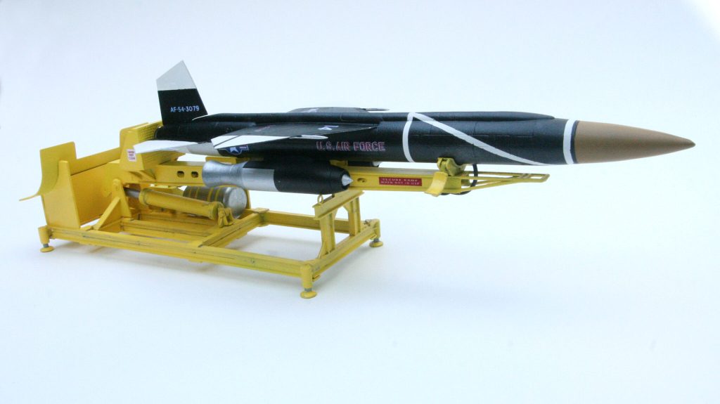
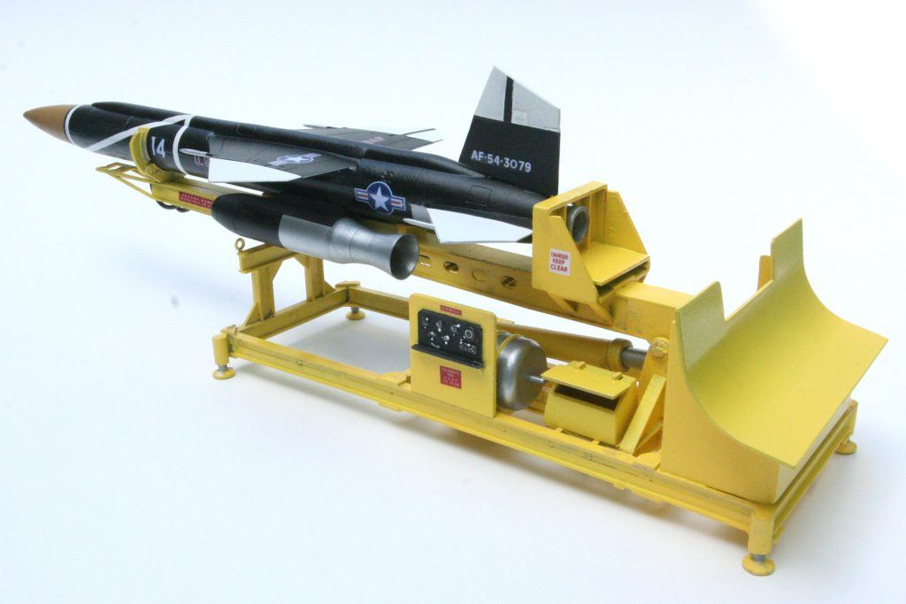
Mounted on a rather large launch gantry, the missile rose from a shelter into its launch position the kit faithfully reproduces the launch stand.

While the missile is drying, start on the launch platform. Dry-fit and clean up the various pieces first. Once the base is complete, you might find the frame is slightly warped—it happens frequently with kits from older molds. Dipping the frame in a bath of boiling water will heat the plastic enough to aid in bending the piece, just a bit. This will help ensure all four legs are level. The gantry is next. While construction is very simple, take time to dry-fit and sand parts so they will be easier to work with. 

Prime the launch pad with a coat of white, then a nice industrial yellow. A light wash of black will make some of the detail pop. To replicate the dials and gauges on the launcher, a cockpit instrument panel decal from the parts box can be cut down. Small excess ejector pin pieces form the back of the gauges. Florist’s wire works well for some of the hydraulic lines that run the length of the launch rail.

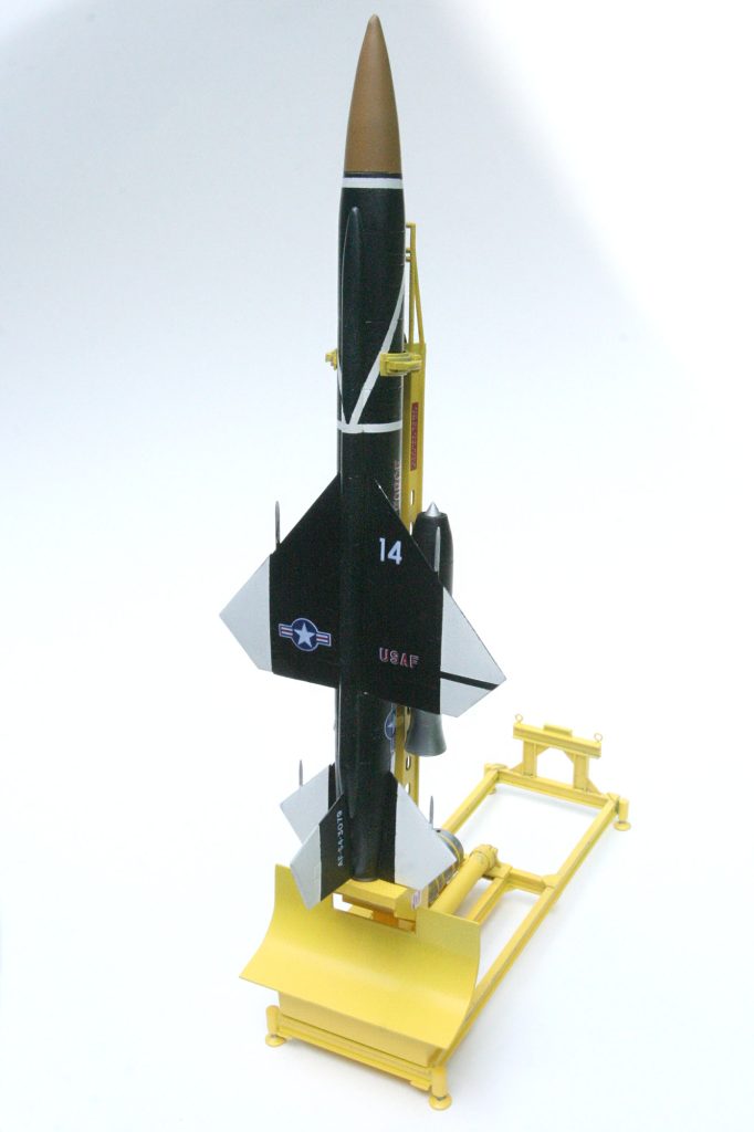
With the launch platform nearly complete, painting the missile itself is next. There are three schemes to choose from. One is an overall gray that was typical of operational missiles and Canadian markings are included for their contribution. A third scheme is more visually interesting, an overall black with white wingtips and geometric striping. Spray the white first, and following your reference photos, mask off the areas that will remain white. There are decals for the white striping, but masking the white before painting the rest of the missile gives a cleaner look. The nose should be a medium tan color. After an overall gloss coat, it’s time for markings. The decals are a bit thick; a decal setting solution will make them settle into the panel lines just fine.
Set aside the missile and turn your attention back to the launcher. The launch rail/gantry assembly snaps into the base, and it can be articulated so that you can display the missile either horizontally or vertically. A few decals, data plates and warning signs complete the base.

Parts are included for a maintenance stand that runs the length of the launcher. It’s a nice addition but we’ll add it to the next one (how could you build just one?).

Back to the missile and some final bits and pieces. Attach the two ramjets to the underside of the main fuselage. Another layer of gloss coat and the missile is ready to be attached to the launch pad. Finally this classic IM-99 Bomarc missile is ready to display. Building this kit brings back a lot of memories, but with the intervening years comes experience. Hopefully your completed missile looks a little sharper than it did the first time. 

Building one of the Luftwaffe’s Wunderwaffen, the Heinkel He 162

A last ditch fighter designed to keep the Allies at bay, jet technology and plywood wasn’t enough. It was however, a unique, innovative design that certainly turned heads.

Too little, too late

By 1944 Hitler had directed the development of new cutting edge technology in hopes of creating a series of Wunderwaffen, “Wonder Weapons,” that he decided could stop the Allies and maybe even … win. The Luftwaffe had long been interested in jet and rocket technology. They would field the first operational jet powered fighter, the Messerschmitt Me 262. While it slashed its way through bomber formations there were never enough to make a real difference. The Luftwaffe had to look at just about anything that could help.

Commanders began the Jägernotprogramm, the “Emergency Fighter Program,” designed to get some of their cutting edge designs off the drawing board and into the air as quickly as possible.

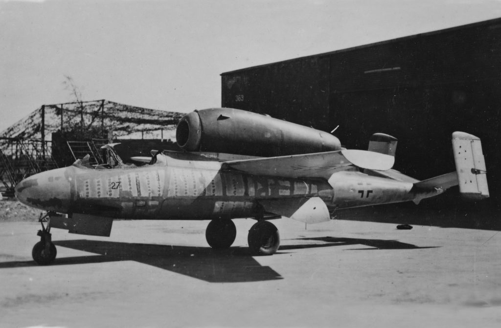
The inspiration for our model is this He 162A-1 found unfinished, at the Bernburg airfield when the base was occupied by American troops in early April 1945. 

One of those designs was the Heinkel He-162 Volksjäger, the “Peoples Fighter.” It was meant to be built quickly from “non-strategic” materials, primarily plywood. Small, even for a fighter, it still packed a punch with two 20mm cannon and later a pair of 30mm guns. A single turbojet engine sat across the spine of the fuselage giving the craft its “hunchback” look as well as a top speed of nearly 520 mph. 

It was a relatively simple airplane to produce, and meant to be simple to fly. Meant to be manned by young Hitler Youth, it actually took experienced pilots to master its handling qualities. During an all to brief operational career the fighter did see combat scoring at least one Royal Air Force fighter on April 19, 1945. Over 120 were built with as many as 600 more discovered in a number of underground factories and assembly areas at the end of the war. Captured He-162s were test flown by a number of allied pilots including Eric Brown, the legendary test pilot from the Royal Navy’s Fleet Air Arm and American test pilot Bob Hoover.

The Kit

There are a number of kits of the He-162 available, the 1/48th scale Tamiya kit was first released in 2006 and has nice detail and a number of great features.

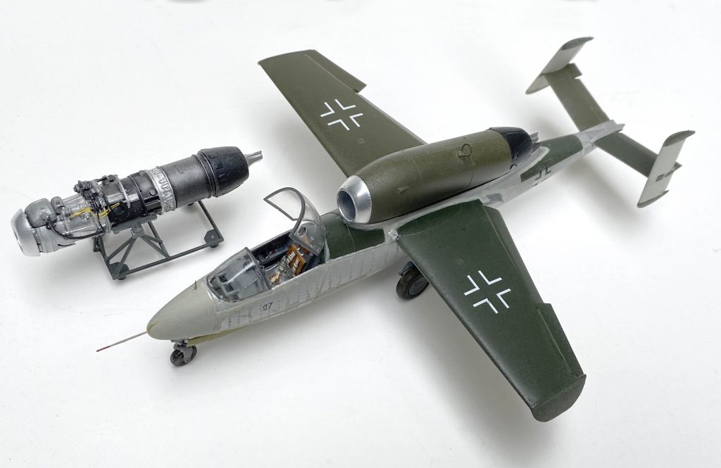
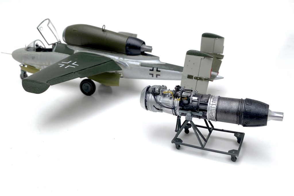
There’s actually an opportunity, to make two models. The kit is engineered to have the builder display the model with the engine bay closed or open to expose a very nice  BMW 003 E-1 turbojet engine. I decided to build the engine separately and display it on its maintenance stand. It should sit nicely next to the finished jet.
Adding some hydraulic lines with a bit of copper speaker wire, stretched plastic sprue and added some extra detail to the engine.
Start with the engine. It’s hard to resist the temptation to add extra hydraulics and a little wiring. The majority of the engine is painted aluminum with the back half a darker metallic color to mimic the discoloration from the heat of the engine. Set the completed engine aside. On to the aircraft itself.
The aftermarket

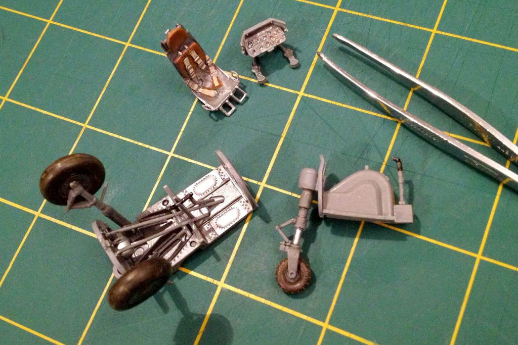
Next come a couple of small sub-assemblies. The cockpit has nice detail but a number of aftermarket parts are available. Quickboost makes a great version of the early ejection seat used in the He-162. Paint the new seat and the separate control panel. The nose gear and wheel well form the lower front end of the cockpit. Sandwich the main landing gear and wheel well, the cockpit and nose gear assemblies along with a large ball bearing (conveniently supplied in the kit) so that the jet will not become a tail-sitter between the two fuselage halves. The completed fuselage needs minimal filler and the overall fit is very good.

The resin seat compliments the rest of the detail in the kit. The instructions are easy to follow and the kit is well engineered.

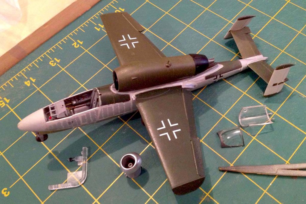
The Czech company CMK makes a nice resin set of the airplane’s control surfaces, flaps, ailerons and a complete tail assembly. The dropped flaps and ailerons, just a little off kilter, all add to the look we’re going for. Using a razor saw cut away the existing flaps. Once they’re removed the resin versions can be set in place, It’s an easy fit. The finished tail assembly fits great too. The seat and control panel are complete but they’ll go in later after the fuselage has been painted.

A different sort of camouflage 

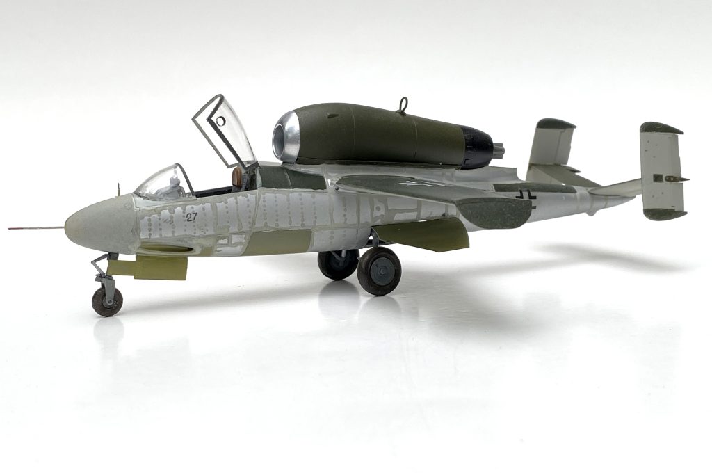
The inspiration for the model came from a photo of an unfinished aircraft found by allied forces at the end of the war. The aircraft had the natural metal surfaces set off by putty over the riveting. The engine nacelle and the wings were painted, as was the tail and other surfaces constructed of other ‘non-strategic’ materials. Mostof the rear of the airplane was plywood and gets a smooth light gray color.

I used a can of Testors aluminum plate that I had tucked away and despite its age it went on very well. The paint is ‘buffed’ after it dries and has a nice sheen to it. Then it’s a fair amount of hand work with a small brush and  ‘Light Gull Grey’ to simulate the putty marks over the top of the Aluminum sections of the fuselage. Unsure of the actual colors, I used the “TLAR” system, ‘That Looks About Right.

The mix of camouflage painted pieces as well as primer colors sets the airplane off and gives the He-162 the appearance of a jet not quite ready to go into battle.

Painting the tail requires a bit of masking to give it that unfinished look, using my photo reference as a guide. By the end of the war Heinkel didn’t seem to go in for the standard ‘splinter’ camouflage most Luftwaffe aircraft had. The Heilkel had to get out of the factory and into the air quickly, no time to waste! The wings and engine nacelle are painted different shades of Luftwaffe Hellgrün (RLM 82) Olivenbraun (RLM 81). By the end of the war there were many slight variations in these colors so The individual modeler has a little leeway.

With the wings and tail on, the jet starts to look like an airplane. Clearcoat, and add what little there were in the way of decals . The markings included in the kit go on just fine.  

A light Gull Gray mimics the putty placed over rivets and seams. The gray green simulates the primer that appears on some of the landing gear doors.

Time to mask and paint the canopy. A lighter grey first, then a much darker grey. I want it to seem as if the interior structure of the canopy frame is lighter than the exterior. The photo I’m using shows the canopy smashed but I just can’t bring myself to destroy that much of the cockpit.  The resin seat is a little big but superglue solves the problem and sliding this early ejection seat down the rails needs a little patience. The detail of the seat and harness really makes a difference in the cockpit.

Another layer of clearcoat once the decals are on and we’re almost done. The control panel slips onto the forward part of the cockpit. A small fine point art pen works well for the small ‘27’ on the forward part of the fuselage. Use white glue attach the canopy and the unique fighter is complete. The finished Heinkel He-162 alongside its power-plant make a nice addition to a collection of some of the Luftwaffe’s more unique last ditch aircraft designs on the display shelf.

The P-80A: Lockheed’s First Shooting Star

Legendary aircraft designer Clarence “Kelly” Johnson designed a sleek, simple jet fighter that helped take America into the jet age.

The Bell P-59 Airacomet was America’s first jet powered aircraft, but it would be Lockheed’s Kelly Johnson who would design the jet that would make it to the flight line first. During the last months of World War II, the U.S. was struggling to catch up to its own Allies as well as the Luftwaffe. The British Gloster Meteor was already in service knocking down speedy “Buzz Bombs” headed to targets in Britain. The Messerschmitt Me-262 was slashing its way through allied bomber formations. America was left tinkering on the cusp of “the Jet Age” at a small air base in the California desert.

With the Bell airplane’s lackluster performance, the door was open for Lockheed to step up. Kelly Johnson and his “Skunk Works” crew would produce an entirely new jet fighter in only 143 days. The clean lines of the P-80 Shooting Star had the look of the future that the fledging “Air Force” was looking for. Clearly the better airplane, the P-80A was still a handful and a number of accidents during testing hinted at a steep learning curve. The P-80 had one toe in the future and one in the past. without an ejection seat, and a little underpowered at first, the jet was quickly improved and would see yeomanlike work during the Korean War as the newly designated F-80C.

But first … 

The Kit

In 2013 Hobby Boss released a Lockheed F-80A Shooting Star, the first of a series of three different versions including an RF-80 and an F-80C. Technically speaking, they’re all the same kit, with the exception of a few new parts for the reconnaissance nose section of the RF-80. However, with a few minor changes, the “F-80A” can be backdated to depict an earlier P-80A. 

In 1948 the newly formed U.S. Air Force changed their designation system so that the P-80 (P for pursuit during World War II), became an F-80 (F for fighter). Initial production versions of the new jet did not have an ejection seat, nor did the airplane have a radar in the nose, the technology hadn’t quite caught up to the era of the jet fighter.

Getting Started

Start with the cockpit painting it an interior “chromate” green (FS 34151). Replace the very nice seven-piece ejection seat with a simpler World War II style seat and harness. A spare resin seat originally meant for a P-47 will do the trick. Behind the pilot, a simple armored headrest can be cut from plastic card. The cockpit assembly sits on top of the nose gear wheel well along with the nose gear strut.

Legendary aircraft designer Kelly Johnson’s sleek, simple design, performed better than its Curtiss cousin, the P-59 Airacomet, the countries first jet fighter. It would be the Lockheed aircraft that would see squadron service.

Place the six machine gun barrels into their corresponding slots on the inside of either side of the nose. Install the intake plates (parts A4 and A5) and sandwich the completed cockpit and wheel well between the two halves of the forward fuselage. Use simple white school glue to help anchor a number of small lead fishing weights in the nose to prevent the airplane from becoming a “tail sitter.” Remember the rule of thumb that if you think you have enough weight, add more.

Making Choices

The model is designed to give the builder a choice in displaying the fighter with the rear removed to show off the early jet engine or as a complete jet. To assemble it in one piece, discard part E19 to help lighten the rear of the airplane. Assemble the two rear fuselage pieces and add the interior exhaust pipe. Add the horizontal stabilizers and attach the completed tail to the forward section of fuselage.

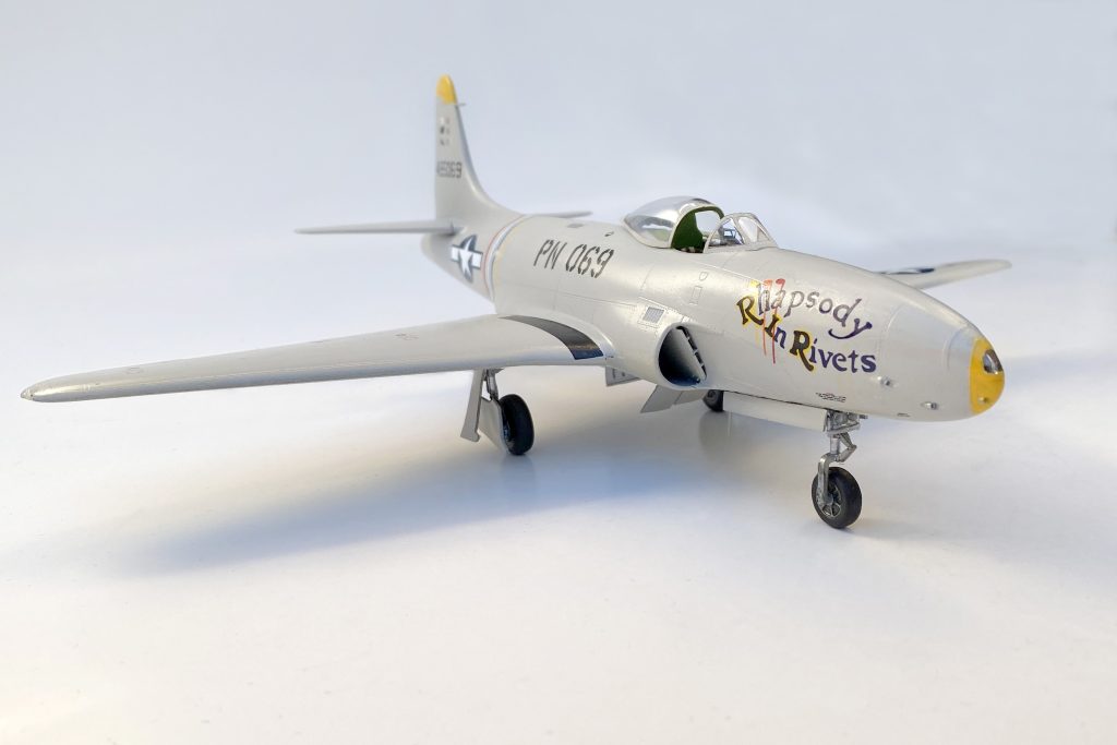
The P-80A had a simpler nose with a single landing light. A little surgery and a bit of clear plastic gives the jet the look of an A-model jet. Technically, he position of the cockpit is not quite right for the early P-80. Changing the position of the cockpit would take major work, a simpler seat helps the look of the earlier version.

On to the wings. Cement the pieces that make up the landing gear bays into their positions on the lower section of the wing, painting them interior chromate green. Before attaching the pieces of the upper wing, dry fit the assembly to the fuselage. The fit is tight and sanding along the wing root edge will be needed to ensure a hint of dihedral. Do not use the underwing hard points, save the 500lb bombs and the larger “Misawa” drop tanks for your Korean War era F-80C. Attach the wings to the fuselage and fill and sand where needed, then set the completed assembly aside to dry.

Put together the landing gear, painting the tires a “rubber” black color and the hubs and struts aluminum. Paint the interior of the landing gear doors aluminum as well.

Backdating Details

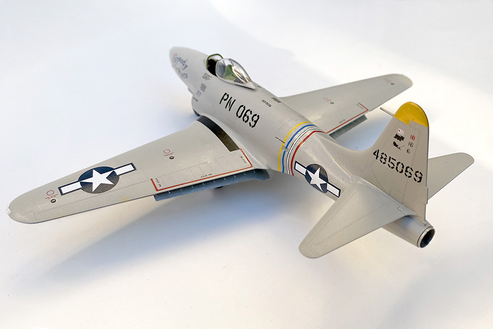
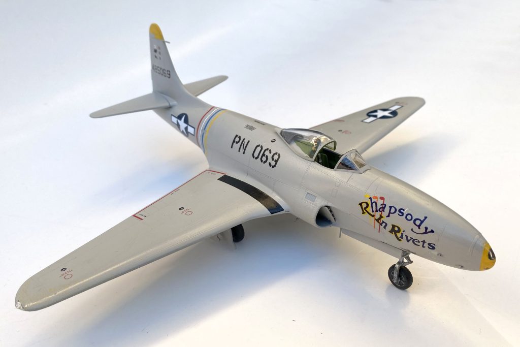
Early production models of the Shooting Star were painted in an overall pearl-gray color (approximately FS 26622). Those early P-80s also had a single landing light in the nose that would be replaced by a radar in later F-80B and F-80C models. Using a liquid mask, brush over the small area on part 62, one of the kit’s clear parts, that fits neatly on the nose of the airplane. Refer to your research to get the size and shape of the area right.

After painting the model and adding a coat of gloss varnish, it’s time for markings. Use the kit decals for its stencils and other basic markings. Weathering should be minimal; these were new and well maintained jets.

Postwar Markings for the Jet Age

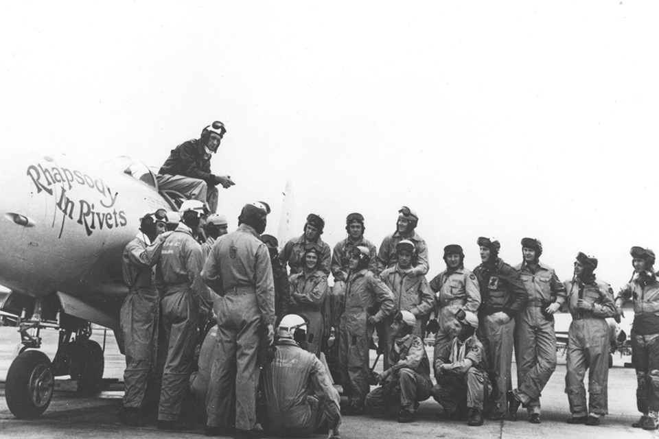
From the spares box, a well-cared for set of aftermarket decals (Super Scale set 48-35) has markings for the P-80A “Rhapsody in Rivets,” belonging to 412th Fighter Group Commander, Col. Bruce K. Holloway. In May 1946, the group was tasked with showing off their sleek new fighters, crisscrossing the country. Holloway, an ace in the Pacific during World War II, displayed his combat victories on the tail of his fighter along with many of his pilots, all combat veterans.

Perched atop his P-80A “Rhapsody in Rivets” 412th Fighter Group commander, Col. Bruce K. Holloway briefs the rest of his group on their next stop during Project Comet, a thirteen day transcontinental public relations deployment. (National Archives)

With decals complete and hit with a light coat of clear varnish, attach the pair of flaps to the wing and  the landing gear, and the two small speed brakes underneath the airplane. Main gear doors are a two piece affair with one part attached to the wing and a second piece attached to the gear strut and tire. Glue in place the single antenna just behind the nose gear bay. The delicate pitot tube, normally seen attached to the leading edge of an airplane’s wing, is located on the forward edge of the rudder.

Mask and paint the bubble canopy, attaching the finished pieces to the cockpit. Pose the canopy slid back to show off the detail in the cockpit. With the cockpit canopy in place, your Lockheed P-80A is now ready to display with your collection of early jet aircraft.

The “Zero Killer” vs. the Luftwaffe

Better known as Grumman’s answer to the vaunted Mitsubishi “Zero,” the F6F Hellcat also prowled European skies, and went toe-t0-toe with the Luftwaffe.

Luftwaffe kill markings on a Hellcat? 

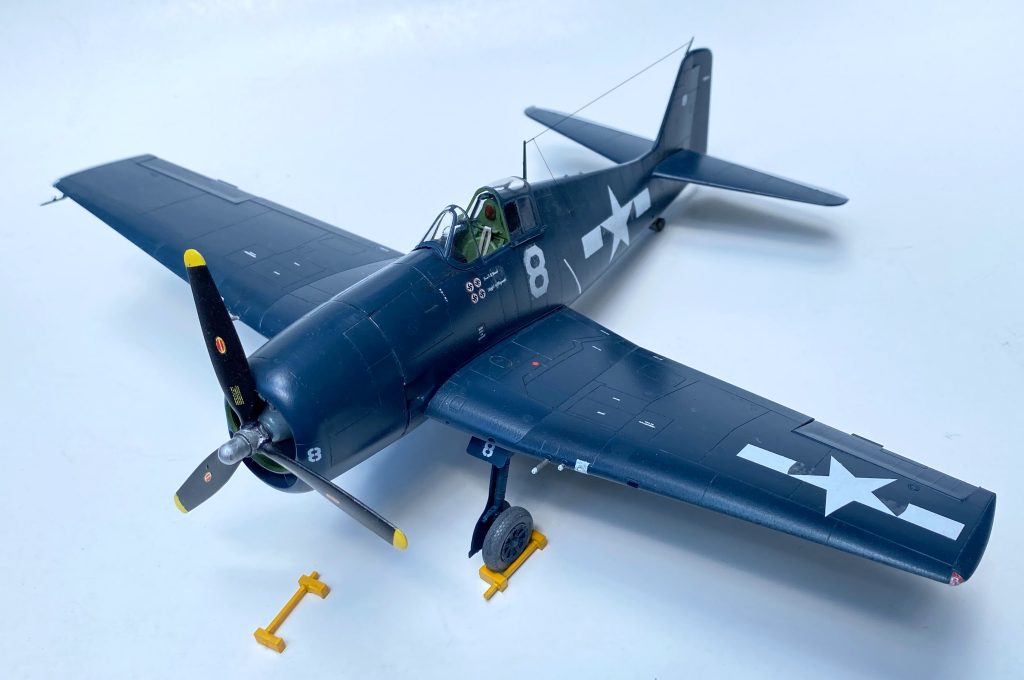
The Grumman F6F is synonymous with the Pacific Theater of World War II. Alex Vraciu, Eugene Valencia, the Navy’s leading ace, David McCampbell and 302 other Navy and Marine Corps pilots, became aces flying the tough fighter. It’s considered by many as the “Zero killer” specifically designed to take on the Japanese fighter that had a near mythic status early in the war. 

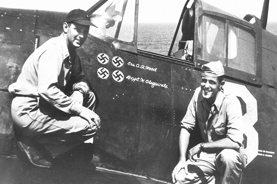
The Hellcat did however, best more than just Japanese aircraft. In August 1944, two squadrons of Hellcats from the escort carriers USS Tulagi and Kasaan Bay were part of  Operation Dragoon, the invasion of southern France, pilots of Observation Fighter Squadron 1 (VOF-1), Ensign Alfred Wood and Lt. (j.g.) Edward Olszewski took turns flying the same Grumman F6F-5 Hellcat, shooting down a total of four German aircraft. The fighter they flew was an early model of the F6F-5. 

The Kit 

The Czech model company Eduard has become known for their crisp detail and accuracy. For the picky modeler who wants to build that earlier version of the Hellcat, an Eduard kit is a great choice. Their “Profipack” early F6F-5 release (No. 8225) makes a great OOB (out of the box) project. Finely detailed resin wheels and a beautiful color PE (photo-etched) metal fret means there’s almost no need to buy extra aftermarket sets.

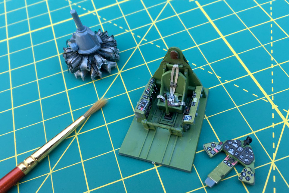
Start with the cockpit and a coat of “interior green” (FS34151) on cockpit walls, seat, bulkheads. Should you decide to use the PE detail set, find some quiet time and unpack your patience. Study the instructions and begin carefully working your way through the (sometimes very tiny) details. Toothpicks and even a small needle are good tools for applying glue to tiny areas. A pair of tweezers is a must.

The etched metal parts and decals for the control panel add detail without the added expense of aftermarket sets.

Align the cockpit between the fuselage halves, glue and clamp where needed. Set the assembly aside and move on to the next step. Overall the fit is very good—only some minor filling and sanding is needed.

The engine is a nice little model all by itself. Crisp detail on the Pratt & Whitney R-2800 is accentuated by a wiring harness from the PE fret. Paint the cylinders an aluminum color, the crankcase grey and wiring black. Use a dark wash to pop out the highlights.

Ensign Alfred Wood (left) and Lt. (j.g.) Edward Olszewski of VOF-1 pose with the Hellcat in which each scored a double victory. (U.S. Navy via Barrett Tillman)

Assemble the horizontal stabilizers. Glue the landing gear interior to the bottom half of the wings and put them together as well. After a little sanding, clean up the wings and stabilizers. Bring the assemblies together and the airplane is ready for the paint shop. Camouflage for this Hellcat is relatively easy. The fighter was painted an overall “sea blue” (FS 25042), including the landing gear. Mask off the cockpit and give the model its color.

Time for some color

A little weathering will add some interest to the monochromatic color scheme. On a cotton swab, ground black, white and a bit of blue oil pastel can create exhaust staining that resembles the way heated metal looks against a darker colored area. A little oil and some fuel stains help give the look of an airplane that spends time outside on a pitching carrier deck. Apply an overall spray of clear gloss and the model is ready for its markings.

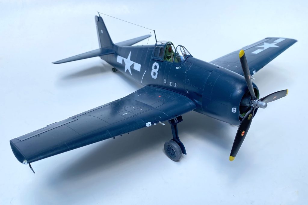
The finished kit looks great and is a satisfying build straight out of the box. Its curious victory markings will definitely turn a few heads.

Two pilots and four Luftwaffe planes down

There are a couple of aftermarket decal sets available that have the markings for Olszewski and Wood’s airplane. National insignia and stencils come from the kit’s decal sheet. The national insignia in particular is composed of just the white star and bars, using the dark blue of the airplane to substitute for the rest of the design. The fighter’s four victory markings and the names of the two pilots will make this Hellcat unique. Take care with the application of the delicate aftermarket decals. Seal the decals with a coat of clear semi-gloss.

The kit includes masks that are pre-cut to neatly fit the clear canopy pieces. The masks are easy to apply and the result is a clean, neat cockpit canopy. Add the assembled landing gear, the smaller bits, pitot, antenna and propeller. Attach the canopy and be sure to slide it back to show off all the cockpit detail.

Your European theater Hellcat is finally ready to display, an interesting addition to your Pacific Cats.

The Vietnam War’s First MiG-Killing F-4B Phantom II

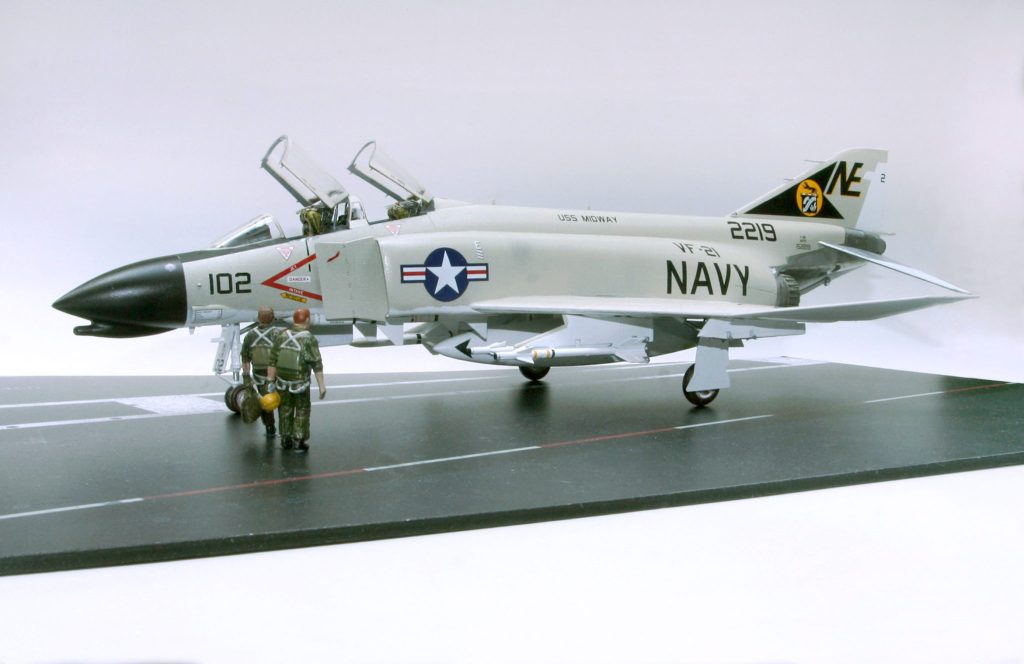
By adding a few aftermarket extras to Hasegawa’s F-4B Phantom II, a ”phan” can proudly add the Navy’s first MiG killer of the Vietnam war to their display shelf.

First Blood

On June 17, 1965 two US Navy F-4B Phantom II fighters met North Vietnamese MiG-17s downing two in a textbook missile engagement. The pair of Navy jets of VF-21 from the carrier USS Midway were crewed by Commander Lou Page, his back-seater Lieutenant J.C. Smith. They were followed by another jet flown by Lt. David Batson and Lt. Cdr. Robert Doremus.

They intercepted the enemy jets, and in an action straight out of the Phantom’s playbook they approached the fighters. The pair of MiG-17s suddenly became four flying close together. Each crew fired a radar guided AIM-7 Sparrow missile, each missile found it’s mark and they were each credited with aerial “kills,” the first American victories of the war.

The missiles worked as advertised, something many would rarely do in future engagements. It would later be discovered that the explosions of the MiGs damaged each of the other jets and probably resulted in at least one other airplane not making it back to base. A third kill that was never confirmed.

The Kit

Phantom “phans” can be a picky bunch when it comes to the myriad nuances among the many versions and upgrades that the McDonnell F-4 Phantom II underwent following its first flight in 1958. Hasegawa’s range of F-4 kits makes even the most detail-oriented modeler happy. First released in the 1980s, its line of Phantoms have remained among the best kits of the type in 1/48th scale. Hasegawa’s F-4B can be built into a fine replica OOB (out of the box), but the popularity of the F-4 means there are plenty of aftermarket detail kits to add to the build.

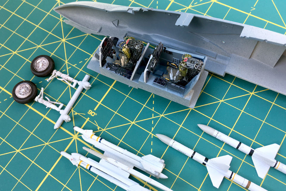
A set of aftermarket resin Martin-Baker ejection seats and a detailed etched metal cockpit interior set give the Phantom’s cockpit extra detail.

Detailing “the office”

Begin with the cockpit. The kit has nice, raised detail for the modeler with a keen eye and a steady hand. There are also two five-piece ejection seats and two detailed pilot figures. For this Phantom, a pair of resin Martin-Baker ejection seats from True Details and an interior metal set from the Czech company Eduard will add detail. Pay particular attention to the rear seat. In the U.S. Navy, the cockpit for the RIO (radar intercept officer) doesn’t have flight controls, so the control stick and throttle aren’t there. Find some quiet time for clipping, bending and cementing all the metal details in place.

While the cockpit tub is drying, it’s time to tackle some of the smaller subassemblies. Put together the landing gear, paint the hydraulic struts for the speed brakes and assemble the centerline external fuel tank. It’s also a good time to tackle the weapons.

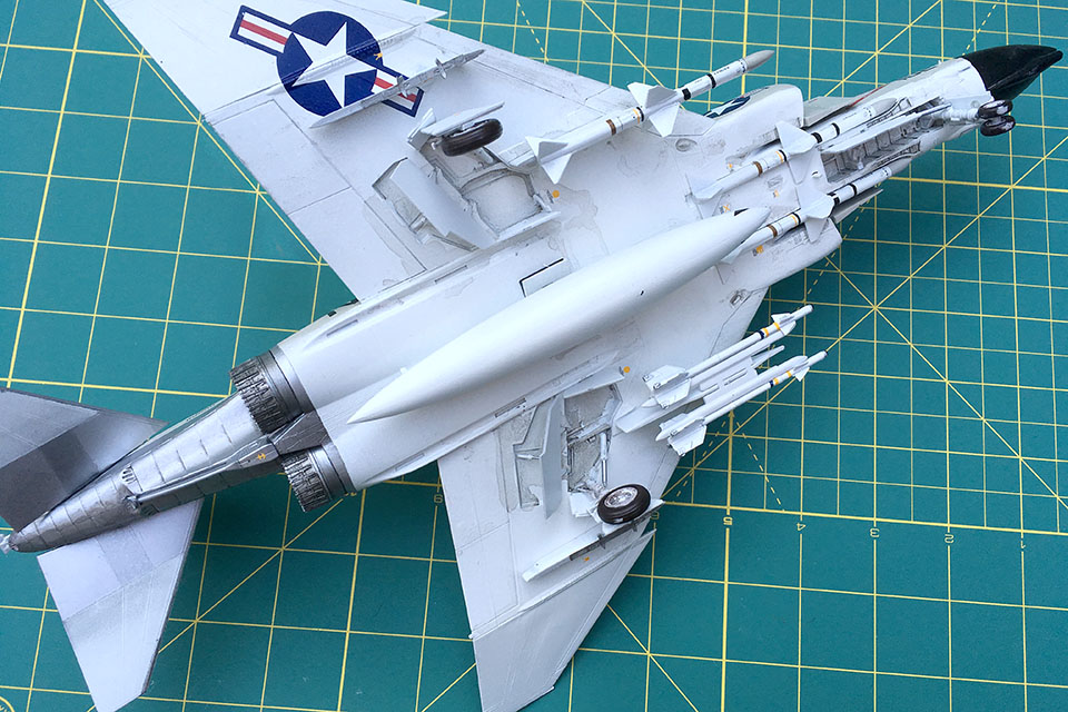
This Phantom was armed with three radar-guided AIM-7 Sparrows and two AIM-9B Sidewinder heat-seeking missiles. Paint the missiles white. The Sparrows have a light grey nose cone. Give the Sidewinders a black seeker head and add a drop of clear gloss to mimic the lens. Two Bobs Decals makes a decal sheet specifically for these kinds of missiles (48-086), helping to give each weapon some visual authenticity. Cement the AIM-9s to the two missile rails that will be attached to one of the inboard wing pylons (G-5 or G-6) and a single Sparrow to the other. Set the completed assemblies aside.

Batson and Doremus’ Phantom was armed with three AIM-7 Sparrow radar guided missiles and a pair of AIM-9B Sidewinders.

With the cockpit complete, glue it to the right side of the fuselage and bring the two halves together. Assemble the top and bottom halves of the wing and attach them to the completed fuselage. It’s a nice snug fit, so there’s very little filling and sanding to get those seams just right. Assemble the engine intakes, but save the two “splitter plates” (D-27 and 28), just forward of the intakes, for later. Fill and sand where needed.

Over time the F-4 upgrades added bulges, bumps and antennas to the airframe. For this early F-4B a couple of those bumps will need to be removed. Using a craft knife, remove the two sensor bumps on the top edge of the vertical stabilizer and sand to shape. Likewise, there are two sensors under each intake that should be removed.

With the bulk of the Phantom complete, it’s time for some paint. The camouflage scheme for Navy aircraft of the time called for white undersides, including the insides of the wheel wells. The upper surfaces are painted light gull gray (FS36440). It technically has a matt finish but you’ll need to use a clear gloss before adding decals. Moveable surfaces—rudder, flaps and horizontal stabilizers (but not the ailerons)—are white on both top and bottom. Add a black matt anti-glare area from the cockpit forward to the radar nose cone, which is painted an overall gloss black.

Add a clear gloss coat to the interior of the wheel wells and speed brakes, using a dark wash to pick out the detail and give these areas a well-worn look. Carrier aircraft spent a lot of time exposed to the weather. Refer to photos from the time and add some daily grime to the underside of the jet.

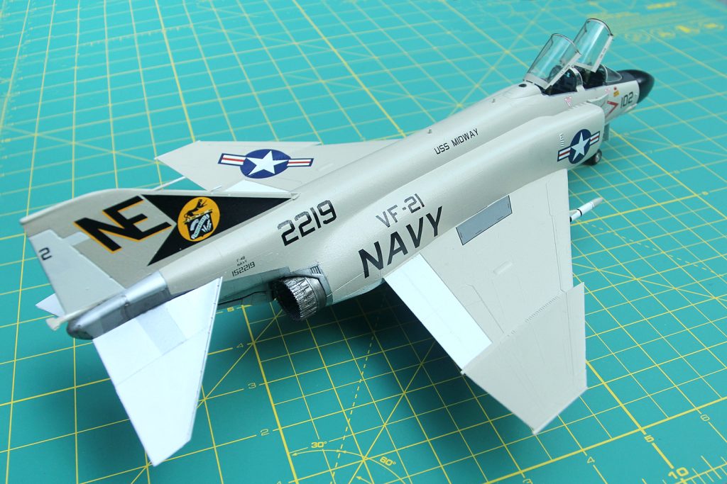
While the Hasegawa F-4B does have the dreaded “raised panel lines,” with a little help it can still be built into a fine replica of the U.S. Navy’s classic interceptor.

The lower section of the rear of the airplane is a metallic, titanium color, as are the inner part of the horizontal stabilizers. Check your resources and the instructions for the correct areas to mask off. Attach the horizontal stabilizers once they’re finished, making sure to have the correct anhedral that is part of the Phantom’s signature silhouette.

Detailed resin extras make a difference

The Hasegawa F-4 kits have a nice level of detail, but the afterburners are inaccurate. Eduard comes to the rescue again with a beautiful set of “burner cans” designed for this F-4B kit. Assemble the pair, painting them a dark titanium color and use a black wash to make the fine resin detail pop. A mix of dark and white pastels can simulate the heat marks inside the afterburner created by the 17,900 pounds of thrust delivered by each of the General Electric J79 engines. Slide the pieces in and cement in place.

The kit comes with two types of canopies. One is a single piece affair, the other comes as four separate pieces, designed to be posed open, showing off all that hard work inside the two cockpits. Mask off the canopy pieces, paint and set them aside.

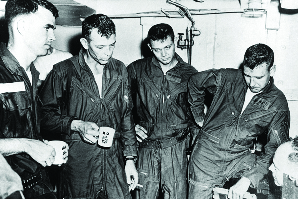
With the camouflage complete, give the model a coat of clear gloss and get to the decals. Furball’s Bravo MiG Killers, Part 2 has markings for both jets involved in the June 17, 1965, engagement described in the Aviation History magazine. The story is told through the experiences of Lieutenant Dave Batson and his RIO, Lt. Cmdr. Rob Doremus. The pair would ultimately down two North Vietnamese MiG-17s that day.

Debriefing Drink. From left: Batson, Lou Page, Doremus and J.C. Smith recount details of the mission for an intelligence officer. Their mugs contained “medicinal” brandy. (U.S. Navy via Batson)

Carefully begin cutting out and applying the decals. Batson’s and Doremus’ names do not appear on the canopy rails of the jet they flew that day, which was assigned to Commander Lou Page and Lieutenant J.C. Smith, the crew flying the other F-4B involved in the engagement. It is not uncommon to fly a mission in a fighter that has someone else’s name on the canopy rail. Detailed artwork included with this set of markings ensures an accurate result. The Furball decals go on easily and with a gentle setting solution look great. Seal the decals with a clear coat and set aside to dry. Don’t forget the tiny MiG-17 silhouette on the splitter plate in front of the engine intake!

Add a modest amount of weathering, especially to the underside and rear of the jet. The GE J79 engines were notorious for their telltale smoke trail, so add a dark chalk pastel color to the rear of the engine’s exhaust where soot would collect, baked against the metal by the hot afterburner.

Adding the final touches

Attach the landing gear, the slightly opened speed brakes and the centerline external fuel tank. Add the two inner wing pylons (G-5 and 6) with the weapons completed earlier—Sidewinders on the left and the pylon with the single Sparrow on the right. The other two AIM-7 Sparrows should rest in two recessed areas under the fuselage. There are four stations designed specifically for that type of missile; be sure to cement the pair of Sparrows into the two forward spots.

Finally, add the clear canopies painted earlier. The flat pane of glass on the forward section actually has a light blue tint. You can get this effect by using a blue highlighter marker on the inside of the clear plastic piece to create the translucent color. Two small hydraulic struts (D-13) hold the canopies open at the same angle. Remember to add the gunsight from the Eduard detail set.

Your Phantom is ready to be next in line for the catapult and another sortie in search of more MiGs!

Named For a Venomous Snake, the Bachem BA-349 “Natter” Proved Deadly Only to its Pilot

By the End of WWII the Luftwaffe entertained nearly any idea to stave off he inevitable

The rocket-powered Bachem Ba-349 Natter was a desperate attempt by the Germans to stem the tide of Allied bombers attacking enemy targets coming in larger and larger numbers during the waning days of World War II. Constructed from plywood and other “non-strategic” materials, it was a curious design that in retrospect probably looked like a better idea on paper.

On March 1, 1945, the only manned launch of the Ba-239 resulted in the death of Bachem-Werke test pilot Lothar Sieber. Most accounts say that the craft left the tower and, climbed to over 1,500 feet when engineers on the ground saw the cockpit canopy fly loose and from the craft. Whether Sieber was injured, knocked unconscious, or struggled to continue the mission, the Natter soared to about 5,000 feet when it rolled over and flew into the ground, killing Sieber.

The Kit

DML/Dragon models from Hong Kong released their 1/48th-scale Ba-349 in the late 1980s. Crisp molding, nice detail, an etched-metal detail set and a complete Walter 109-509A rocket motor make this simple kit a gem. The fuselage is split so that it can be displayed showing off the power plant. This version of the kit comes with a simple maintenance stand, two mechanics and a display base.

Start with the front end of the aircraft. The cockpit is simple and straightforward, much like the real thing, paint it a medium grey with aluminum details and a small black control panel. Add the seat belts that are part of the metal detail set included in the kit. Beware, as some of the parts are very small and delicate. Care should be taken when removing them from the trees, and then be even more careful that they don’t disappear during assembly. The rocket motor is a combination of metal from the etched fret and a number of other delicate pieces. Patience is essential here, but pays off in a nice detailed part of the finished model. 

A manned shotgun shell

The rocket’s only armament was a “shotgun” load of as many as 55 explosive rockets that would be fired into the packed formations of Allied bombers. Once the single pass was complete, the craft would come apart “ejecting” the pilot to parachute back to earth, ready for the next sortie. Essentially the “Natter” was a manned artillery shell. The rocket nose of the model is represented by a single flat piece. Paint it the same gray as the rest of the forward section, and use a black wash, to pick out the details.

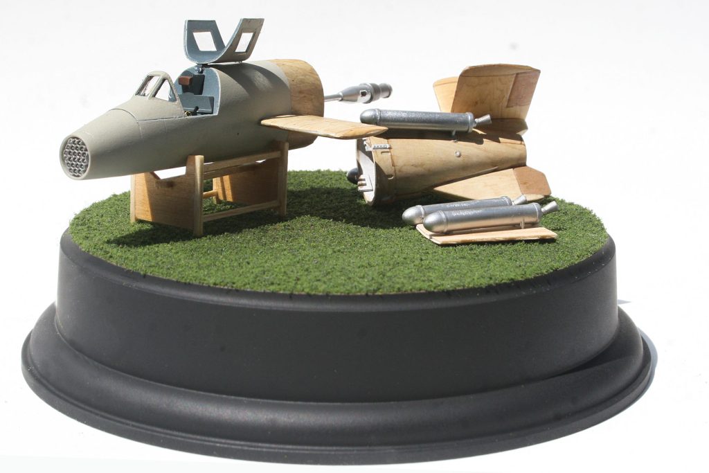
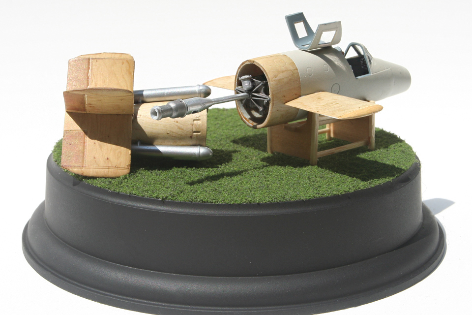
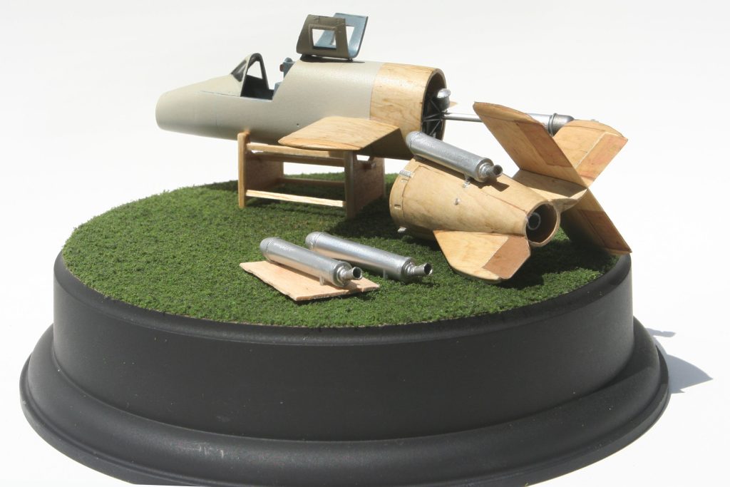
Displaying the model with the rear section detached, gives a nice view of the unique rocket motor.

Replicating “non-strategic” materials

The Natter was made primarily of plywood, and the wooden finish makes for an interesting challenge. HGW Models from the Czech Republic sells a number of decal sets in a variety of wood tones. The decals are translucent and require a base coat—white or a pale tan works well. The film is very, very thin. Careful attention and that all-important tool, patience, is required. Measure twice, cut once when trimming the decal for its spot on the aircraft. A good approach is to make a series of templates for the plywood panels, then cut the shape and apply. The result makes for a very interesting, realistic finish. 

The airplane has four booster rockets to give the main Walter 109-509A rocket motor, the boost it needed to get to the bombers.

Mask and spray the canopy. It’s a thick piece that benefits from masking both the inside and out. Attach it to the forward section of the fuselage. Just tack the main section of the canopy in place to protect the cockpit from the grey primer that comes next. The primer color of the forward section and the natural plywood of the tail help give the appearance of a Natter being assembled before delivery and an operational sortie. Spray the fuselage with a coat of semigloss to protect the finish. Attach the rocket motor, and the forward section of the Natter is complete. The rear will be entirely plywood, finally completed and sprayed with a lacquer coat. Carefully pick out the metal details with a small brush. This version of DML’s kit has a wooden support stand to display the finished model (another version includes the entire launch tower). The stand is very simple, sprayed and given a wood grain finish. The shapes are also simple enough to pull out some thin balsa and basswood to build your own support stand. After a light varnish, the Natter has a place to rest. Assemble and paint the four booster rockets a dark steel metallic color, and attach them to the rear section.

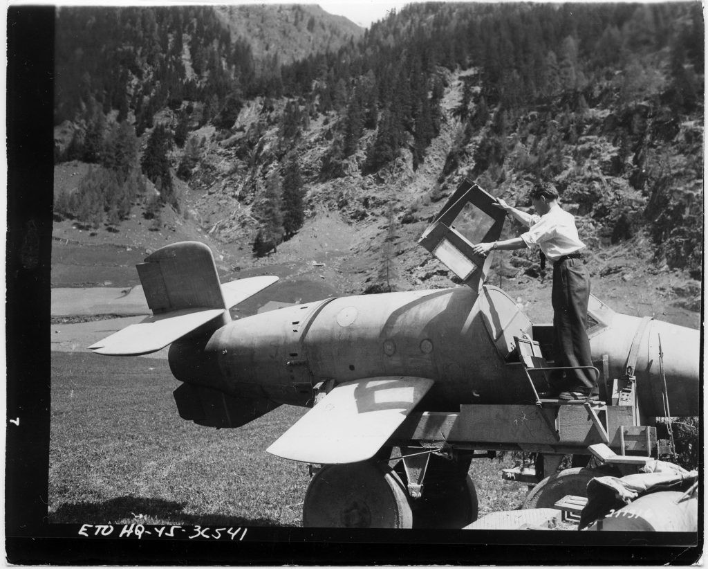
A German engineer from the Bachem-Werke, takes a look at a Ba-349 before showing it to a group of American military personnel that found a number of the rockets at an assembly area in May 1945.

Captured and studied

The kit comes with a round display stand that was painted flat black and a coat of clear varnish. “Grass” was created using materials from a diorama kit found at a local craft store. Displayed unassembled, it’s sure to be studied on the display shelf the same way allied engineers did as the war came to an end.

Your Ba-349 Natter is now ready to take its place alongside those other last-ditch Luftwaffe oddities that continue to fuel the question “what if…”

Take a T-28D “Trojan” from a Training airplane to Secret CIA Attack Fighter

Designed as a replacement for the venerable T-6 Texan trainer, the North American T-28 Trojan proved to be more than just a versatile primary trainer.

With a more powerful engine and reinforced wings, the North American T-28 Trojan could also double as a potent ground-support fighter. The Trojan’s capabilities were not lost on a number of smaller countries looking for an economical addition to their air forces. Armed versions of the T-28 saw action in many hot spots during the Cold War.

The Kit

Roden, a small model company based in the Ukraine, has become popular with modelers for its detailed kits, excellent decals and interesting subjects, offered in a variety of scales. Its T-28 is no exception. The 1/48th-scale Trojan has been released as a primary trainer, an upgraded T-28C and the ground-attack T-28D, complete with a nice variety of weapons.

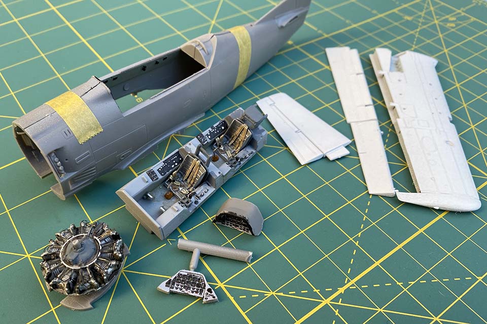
Start with the cockpit. Paint the interior a light aircraft gray. Take care with the control columns, as they are delicate and require a steady hand while removing them from the parts tree. The addition of a couple of resin seats from Quickboost, and etched metal seat belts add the right amount of detail to the cockpit.

Next, move on to the engine. Paint the engine cylinders an aluminum color and the center engine casing a primer gray. A dark wash helps the detail pop. Attach the completed engine to the firewall.

While the cockpit and engine dry, assemble the two-piece flaps, ailerons and rudder. Along the part that makes up the lower wing, open up the small holes where the weapons pylons will be attached later. Put together the wings and set these pieces aside.

The kit already has plenty of detail but a pair of aftermarket resin seats and seat belts give it a little bit extra.

The kit’s landing gear, especially the nose-gear strut, is delicate. Invest in an aftermarket metal landing-gear set and resin tires. Paint the gear aluminum with a glossy chrome color for the oleo section of the strut itself. Tires are a deep rubber color with aluminum-colored hubs and brakes. Once complete, set the gear aside.

Sand and dry-fit the piece that forms the underside of the fuselage (part 22B). Bring the fuselage halves together, gluing the completed cockpit in place, then add 22B to complete the basic fuselage.

In order to make the Trojan sit correctly on its tricycle landing gear you need to add extra weight up front. The space between the cockpit and the engine’s firewall is perfect for enough lead fishing weights to do the job. A good rule of thumb is that if you think there’s enough, add more. Glue the engine and firewall in place and add the cowling, completing the fuselage.

Attach the wings and reach for the putty—some seams along the wing root and under the nose of the model will require filling and sanding. Aside from this area, the fit throughout the rest of the kit is good.

Heading For the Paint Barn

Camouflage for this airplane is the same standard paint scheme used on most U.S. Navy aircraft of the 1960s. The undersides and weapons pylons should be painted insignia white (FS 17875). Upper surfaces are light gull gray (FS 36440). Mask off the cockpit and paint the undersides of the airplane first.

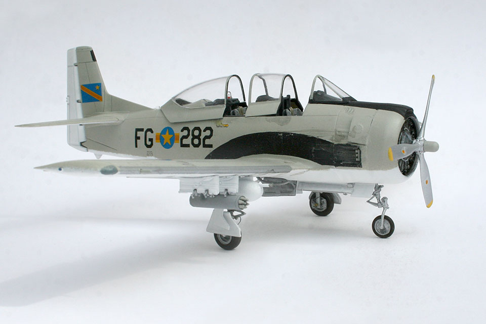
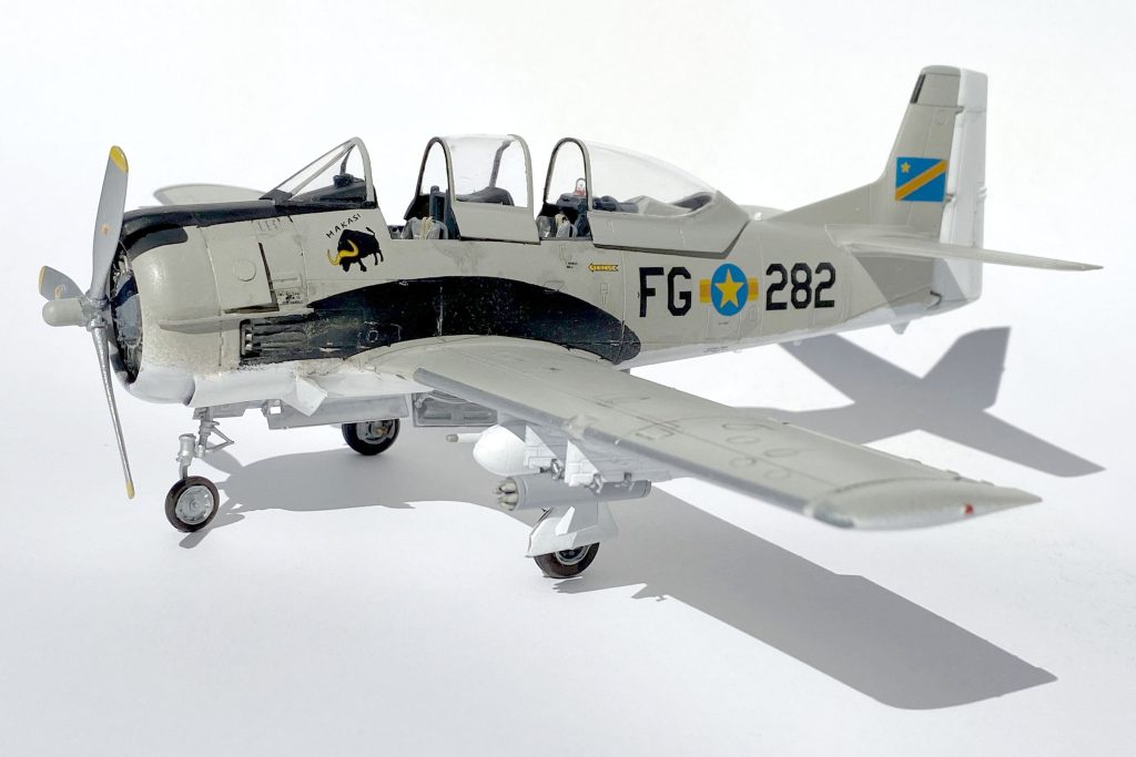
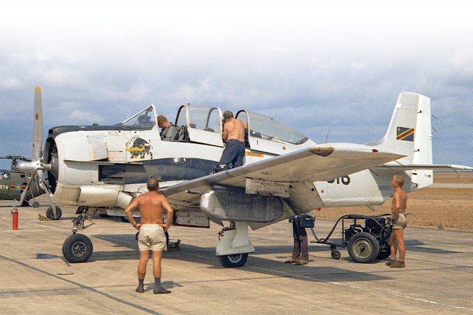
While the paint job is a standard Light Gull Gray over white, the markings for this “secret” fighter carry the unit’s bull insignia taken from the local “Makasi” brewery.

Typical of Trojans painted in lighter colors is a black area painted along the side of the fuselage. The shape curves back from the engine exhaust to the trailing edge of the wing. It helps disguise the side of the fuselage that collects dirt and staining from constant use. Draw out the shape using the reference illustration in the instructions to create a mask and paint the area flat black. Mask off an anti-glare panel from the cockpit windscreen across the top of the engine cowling and paint that black as well.

Secret Set of Markings

Once the painting is complete, attach the rudder and horizontal stabilizer, flaps and ailerons. The flaps are designed to be fitted in a “dropped” position to give the model a more natural look. Spray a clear gloss coat over the model and it’s ready for a set of decals. The Roden kit contains markings for three different aircraft: a U.S. Air Force trainer based at Eglin Air Force Base in Florida; a camouflaged Trojan that served with the 606th Special Operations Squadron, based in Thailand during the Vietnam War; and an aircraft that was part of the CIA-backed Air Force flown by Cuban exiles during the civil war in the Congo in 1964. After the decals have been applied and a clear coat has sealed the markings, attach the landing gear, gear doors and speed brake. The main landing gear doors are a two-piece affair that benefits from carefully studying the instructions and a reference photo or two. Next, attach the pylons and weapons. There’s a good selection to choose from—rocket pods, two different types of machine gun pods, 250-pound bombs and a pair of SUU-14A bomb dispensers.

On a remote airstrip ground crew prepare a Makasi T-28 Trojan for a mission. (T-28 Trojan Foundation)

With the model nearly complete, it’s time for some moderate weathering, typical of to weather in Central Africa, before adding the last few pieces to this secret T-28. Photos of T-28s that provided ground support in the Congo show that a typical loadout consisted of machine gun pods and rockets. Once the weapons are attached, add the three-piece canopy using white glue or a cement designed for clear parts. Make sure to attach the pieces in an open position to show off all that cockpit detail.

Once the final pieces are attached, this CIA veteran T-28 is ready to shine on a clandestine section of your display shelf.

Building a Falklands Sea Harrier

The Hawker Sea Harrier became a well deserved legend during the Falklands War. With a little extra work the 1/48 scale Airfix kit deserves a place in your collection.

In the late afternoon of May 1, 1982 Royal Naval Air Service Hawker FRS-1 Sea Harriers went up against enemy fighters for the first time during “Operation Corporate” the war to take back the Falkland Islands. The revolutionary fighter had never seen combat before. It was a unique aircraft, able to take off vertically and transition to level flight. It would prove more than a match for Argentine Mirage, Dagger and A-4 Skyhawks in the freezing skies of the South Atlantic. By the end of May, the Sea Harriers had dispatched 20 Argentine aircraft for no loss, in air-to-air combat.

The Airfix Sea Harrier is an over 40 year old kit, but it still deserves a spot on your display shelf

The Kit

The 1/48th-scale Airfix Sea Harrier FRS.1 has been around for quite a while. Although there have been some stellar new releases—I would love to see an retooled Airfix kit! —for now I’ve concentrated on adding a little after-market detail to improve this build. Some scratch-building skills will come in handy for this project.

The detailed resin seat, intakes and detailing the Auxiliary Power Unit helped the overall look of the build.

I replaced the stock seat with a resin version, and the rest of the cockpit was enhanced with an etched-metal detail set. The other bumps, tubing, wiring, etc. came from my parts box. Note that the gun pods need some additional detail: I added a new gun muzzle and drilled out the four vents just aft of the muzzle. I also opened up the auxiliary power unit exhaust vent, on top of the fuselage, and added a set of aftermarket intakes to accurately depict what a powered-down engine would look like. An AIM-9L Sidewinder came from the parts box.

Taking a break from all that fine detail work in the cockpit, I spent some time finishing off some of the smaller bits, so they would ready for final assembly. These included the landing gear, the extra fuel tanks, the pylons and the AIM-9 missiles.

Once the cockpit is complete, the wings and fuselage come together. Then it’s time for filling and sanding—plenty of it. But that’s what you expect with a kit that’s some 30 years old.

With major sub assemblies complete, it’s time to get it all together.

Air War South Atlantic

The Hawker Harrier’s introduction was an aviation milestone, combat during the Falklands War in May 1982 that gave the fighter its “street cred.” At the heart of the Harrier’s unique capabilities is its Pegasus engine. Four nozzles rotate to direct the exhaust, putting the “vertical” in VTOL. Cooler air leaves the forward two nozzles, while hotter exhaust comes from the rear two. The rear pair should be painted a smoked metallic color, and the forward nozzles should be a color similar to the jet’s camouflage tone. During the Falklands War, the first group of Sea Harriers to head from Britain to the South Atlantic lost their more visible dark sea gray and white along with their colorful squadron markings in favor of overall dark gray. The new paint scheme was applied during their voyage south.

Lieutenant Clive Morrell steps out of the cockpit of “Black 14” onboard HMS Hermes. Morrell was returning from a sortie where he had just downed an Argentinean A-4Q Skyhawk on May 21, 1982. (MoD Crown Copyright)

With wings attached to the model, the cockpit masked off and filling and sanding complete, it’s time for paint. I chose an overall dark gray that fits my reference material. Once I applied a coat of a gloss varnish, it was time to start on the kit’s excellent decals. Though they’re thin, they respond well to a little decal softener, snuggling into all those nooks and crannies.

Markings for a Combat Vet

The kit comes with a choice of markings: an aircraft from the Indian Naval Air Force or XZ457 (“Black 14”), a Royal Naval Air Service Sea Harrier that flew from the carrier HMS Hermes during the Falklands conflict and was credited with two Argentine IAI Daggers and an A-4 Skyhawk. Interestingly, both Black 14 and the Indian jet spent time aboard Hermes, as the carrier was sold to India in 1987.

I took care of the trickier decals under the wings and some other hard-to-reach places before adding underwing stores and the landing gear. Much of the stenciling on this jet was painted over as Hermes headed into combat. Note that special care is required when positioning the landing gear to get the jet to stand evenly on all four points. Take your time with this process.

A little weathering and we’re ready for the deck of HMS Hermes.

Finally, superglue the remaining antennas in place, then add a little weathering, and your Harrier is complete. With patience and a little finesse, this classic Airfix kit will make a nice addition to your collection.

Building Stalin’s “Flying Tank”

Designed to support Soviet ground forces, the Ilyushin Il-2 was produced in greater numbers than any other airplane in history, bad news for German armor rumbling across the battlefield.

The Flying Tank

Designed by the legendary Sergey Ilyushin, the Il-2 was designed to support Soviet ground forces and was nicknamed Shturmovik (штурмовик), a generic term for a ground-attack aircraft that became synonymous with the airplane. Referred to as “Stalin’s Tank” and “Hunchback” because of the shape of the cockpit, the heavily armored airplane packed a solid punch. A big, broad wing gave the airplane the lift it needed to carry enough rockets and bombs to hunt German panzers across the broad plains around Kursk in July and August 1943. Solid construction helped it survive both flak and encounters with the Luftwaffe’s best.

The airplane was introduced to frontline service in May 1941 just weeks before the Operation Barbarossa, the invasion of the Soviet Union by Nazi Germany on June 22, 1941. While only 249 aircraft were available at the time, by the end of the war over 43,000 had been built, one of the most produced aircraft in aviation history. The “Flying Tank” was built in a number of types including a two seat version with the addition of a rear gunner. 

The Kit

The Academy 1/72nd-scale Sturmovik was released as both a single-seat Il-2 and as a two-seat Il-2M. it includes a variety of armament including air-to-ground rockets, a pair of 220 lb bombs, and small bomb bays that would contain over 100 anti-armor bombs. The kit has very nice detail and good fit, needing a minimal amount of filling and sanding.

First Things First

This kit is the single seat Il-2 but the start of the build is the same, the cockpit. Fit the seat, rudder pedals and the large gas tank situated behind the pilot’s seat to the cockpit floor. A couple of strips of painted masking tape can work as a set of seat belts and a shoulder harness. The cockpit assembly sits on the center section of the lower wing. The wing/cockpit assembly fits into the two fuselage halves when they’re glued together. Don’t forget to install the control panel before cementing the cockpit and lower wing into place.

The completed cockpit assembly sits on top of the center section of the lower main wing. The rockets and bombs are tiny pieces, be careful not to lose one!

At this point the instructions call for the engine exhaust (parts F9) to be glued from the inside of the fuselage halves. A better choice is to wait until the fuselage is painted, trim the parts and install them after painting. The direction sheet also shows where wing-mounted machine guns (parts F96) fit into the wing. Again, wait until later to add these tiny parts.

Make Sure Things Fit

Take some time to dry-fit the rest of the wing. Keep an eye on the fit at the wing root. With the wing attached to the fuselage, add the landing gear bays to their positions on the underside of the wing. Fill and sand the fuselage and wings; smooth out the seams around the landing gear, wing root and fuselage; and then set the assembly aside.

Hungarian pilot A.V. Chuvikov of the 606th ShAP (Shturmovik regiment), 214 ShAD (Shturmovik Division) gets some last minute instructions. His Il-2 is emblaisoned with “Za Otradnova” (For Otradnov) a fellow pilot who had been killed in action.

Put together the tires, painting them flat black with aluminum-colored hubs. Assemble the two 500-pound bombs, painting them black as well. This Il-2 is also armed with eight unguided rockets on launch rails beneath the wing. Paint the rockets dark gray with silver tips and the individual rails steel. After assembling the propeller, paint the blades black and the spinner dark green.

Painting

Now it’s time to mask off the cockpit and paint. The Academy kit has a choice of 11 different aircraft markings in a variety of camouflage schemes. This one will be painted with a medium olive drab and a very dark, greyish-green pattern on the upper surfaces with light blue on the undersides.

Once all the masking has been peeled away to show the completed camouflage, a number of “tiny bits” need to be added. The trim tab actuators are separate pieces that require special care when gluing each (very tiny) piece onto the wings and tail surfaces. Touch up the camouflage and spray the model with a coat of clear gloss to prepare it for the decals. This Sturmovik had the words “За Отраднова” (For Otrandova) painted down the side of the fuselage in honor of a fellow pilot named Otrandov, probably killed in battle. Note that the iconic red star insignia does not appear on the top of the wing, only on the undersurfaces and tail.

Underneath should see a little weathering too. streaks of oil and soot from many a fired anti-tank rocket can be created with artists oil paint thinned to a light wash.

A modest amount of weathering lends some authenticity to this Il-2. These aircraft spent a lot of time in the field and would have seen plenty of use. Chipped paint along the left wing root shows where crew and maintainers spent time getting in and out of the airplane. Exhaust stains and soot under the wing mark where rockets had been launched at previous targets. All these things will give the model plenty of interest.

It’s time to install the landing gear. Be careful clipping these pieces from the “parts tree,” as they are delicate and can easily break. Carefully cement the two braces that make up the landing gear struts into the “pods” underneath the wing. The fit is tight­—dry-fit a couple of times before final assembly. Once they set thoroughly, add the tires, which fit neatly on the forward struts. The tires come slightly flattened to show the weight of the aircraft once it’s completed. Make sure the airplane sits correctly before adding a small bit of cement to the tires, completing the landing gear.

At this stage you can insert the two exhaust stacks into place. Carefully slip those tiny machine gun barrels and longer cannon barrels onto their positions at the wing’s leading edge. Paint them a light gunmetal color. Add the propeller and set the nearly completed model aside.

With a very sharp knife mask the three-part clear canopy. Modeler’s masking tape is a good choice for those with a steady hand.  Pre-cut masks are another option and can be obtained from a number of retailers. With the clear parts painted, use white glue, or a cement formulated for clear parts, and add the canopy.

Beat up the paint job a little. Chipped paint to show wear and tear on an airplane that saw plenty of use can be created with a fine brush and colored pencil.

Time to load this tank killer up. Attach the eight unguided rockets and launch rails to their positions under the wings. Bomb braces have positions between the landing gear and fuselage. Add the braces and then attach the bombs.

Finally, mount the radio antenna just behind the cockpit and this Il-2 is ready to hunt for German panzers across the Russian steppes.

Building Mitsuo Fuchida’s Pearl Harbor Command Post 

The Nakajima B5N2 Kate was the best torpedo bomber in the Pacific. The airplane also was the aerial command post for Japan’s “Day of Infamy.”

A talented young officer in the Imperial Japanese Naval Air Service, Mitsuo Fuchida was chosen by Vice Admiral Chūichi Nagumo to coordinate and lead the attack on Pearl Harbor. From his place in the center seat of a Nakajima B5N2 “Kate” he would be able to see the state of the harbor’s defenses and command his waves of attacking aircraft. 

Released in 2001, Hasegawa’s “Kate” has been offered in a number of guises, as a torpedo plane, a version with folding wings and one with a single armored piercing bomb. That kit, their first offering, includes markings that are not for the more popular torpedo plane, but for Fuchida’s command aircraft. The “tip of the spear” of the Pearl Harbor attack.

The detail is typical for Hasegawa, accurate to a fault. Begin with the cockpit, paying close attention to the plenty of small parts that make up the aircrew’s “office.” It was common for different manufacturers to have their own particular interior paint color. Nakajima’s greenish gray, (often called Nakajima Interior Green), is different from the greenish blue that was typical for Mitsubishi’s aircraft. Paint the cockpit parts and get started.

The control panels have nicely raised detail, but decals are provided for some of us without the talent for painting tiny dials and switches. The only extras that are needed are seat belts for the three crew positions. 

The three man cockpit is made is made up of thirty-one separate pieces. Decals for the control panel and aftermarket seatbelts give it some added interest.

Once completed, the cockpit assembly forms a tub that fits between the fuselage halves. The fit is very good, but it pays to dry-fit pieces first. Once everything is together, set aside the completed fuselage.

Next assemble the bomber’s engine painting it black. Cement the engine to the firewall and drybrush an aluminum color over the engine’s cylinders to make the detail pop. Paint the main crankcase a medium gray. Paint the cowling and the forward firewall flat black. On many Japanese aircraft a flat black color extends from the cowling to the pilot’s windscreen. The color acts as an anti-glare panel. Paint the cowling and glue it in place setting the completed assembly aside. 

It’s time to attach the large broad wing to the fuselage. Again, the fit is very good and requires minimal filler and sanding. 

Moveable surfaces, rudder, ailerons and the horizontal stabilizer were fabric covered and should be painted in the same color as the bomber’s interior. The rest of the airplane was left natural metal. Upper surfaces should be a dark green color. Photos from the time show many carrier-based aircraft with a fair amount of chipping and wear of the dark green. Images of what is purported to be Fuchida’s “Kate” show the camouflage, hastily applied without primer, flaking off from exposure to the harsh weather at sea.  

This is purported to be a photo, taken from newsreel footage, of Fuchida’s Kate returning to the carrier Akagi after the Pearl Harbor attack. Notice the paint chipping. (National Archives)

There are a couple of ways to replicate the chipped effect. One is to spray common hairspray to the natural metal color, letting it dry before painting the dark green color. There are also a number of “chipping fluids” on the market that can be brushed on or sprayed in much the same way. Once the chipping solution and dark green camouflage have been applied, a cocktail stick and an old toothbrush can be used to chip away at the camouflage color. Wet the toothbrush and start scrubbing the various seams and panels removing the green paint in much the same way as the harsh weather did on the real thing. 

Take your time and experiment first before going all in on the model, it is a bit of an art form. Once you’re satisfied with the look, set aside the aircraft to dry thoroughly. 

Next, spray a light gloss varnish to prepare the model for the decals. Markings are very simple affair, a large Hinomaru (the classic large red disc) appears in six positions: top and bottom of the wings and either side of the fuselage. The tail is painted red with three broad yellow stripes on the rudder along with the code “AI-103” signifying that it is the commander’s airplane from the wing aboard the aircraft carrier Akagi. A coat of a dull varnish seals the decals.

The finished Kate doesn’t look as good as new, but that’s the idea behind the weathering.

Next, assemble the landing gear, painting the tires a black rubber color. The gear struts and landing gear doors should be a natural metal aluminum color. Add some mild weathering, oil and fuel stains. Keep the weathering to a minimum, crew members would have taken excellent care of their aircraft on the long voyage across the Pacific. 

The kit gives the modeler a choice of a one-piece canopy or positioning it open to show off that detailed interior. The clear pieces are thin, be careful not to crack the plastic. Invest in a set of precut adhesive masks for the canopy. A number of brands are available designed specifically to be used with the Hasegawa kit. Mask off the different canopy pieces and paint then the same dark green as the rest of the aircraft. Let the pieces dry thoroughly before removing the masks. Pay close attention to the four canopy pieces and how they fit together when slid open.